
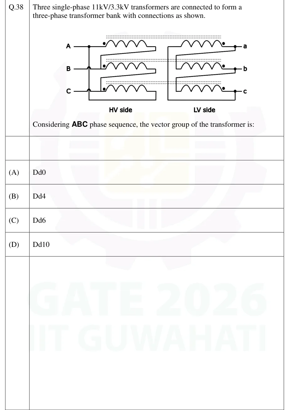
Three single-phase 11kV/3.3kV transformers are connected to form a three-phase transformer bank with connections as shown. [Figure: HV side has three single-phase transformer primary windings, one per phase, fed from lines A, B, C, each winding's dotted terminal connected directly to its own line (A, B, C respectively); a diagonal jumper connects the undotted (finish) end of the A-winding to the dotted (start) junction of the B-winding, and another diagonal jumper connects the finish of the B-winding to the start junction of the C-winding; the finish of the C-winding returns, via a bus that runs down the left side of the HV block crossing (without connecting, shown as wire hops) the B and C line taps, to the A line junction — this closes the HV windings into a delta A→B→C→A. Each HV winding is drawn on the same magnetic-core row (linked by a dashed line denoting the shared core) as one LV winding: row 1 = HV-A with LV winding for terminal a, row 2 = HV-B with LV-b, row 3 = HV-C with LV-c. On the LV side the windings are mirrored left–right: each winding's dotted terminal is on the right, tied directly to its own line (a, b, c); a diagonal jumper connects the dotted/line junction of a to the undotted (finish) end of winding b; another diagonal jumper connects the dotted/line junction of b to the finish end of winding c; the finish end of winding a is returned, via a bus running down the far-left side of the LV block (crossing, without connecting, past the b and c rows) and along the bottom, up to the dotted/line junction of c — closing the LV windings into a delta whose loop order is a→c→b→a. Both sides are labelled 'HV side' and 'LV side' respectively.] Considering ABC phase sequence, the vector group of the transformer is:
 Tap to open full size
Figure description
Three single-phase transformer units drawn as three horizontal rows. In each row the primary (HV) winding is on the left half and the secondary (LV) winding is on the right half, magnetically linked (same core) as shown by a dashed line spanning that row. Row 1: HV winding fed from line A (dot at the A-line end) coupled to an LV winding terminating at line a (dot at the a-line end). Row 2: HV winding fed from line B (dot at B) coupled to LV winding terminating at line b (dot at b). Row 3: HV winding fed from line C (dot at C) coupled to LV winding terminating at line c (dot at c). HV interconnection (forming a delta): the non-dot (finish) end of the row-1 (A) winding is joined by a diagonal wire down to the dot/start junction of the row-2 (B) winding; the finish of the B winding is joined by a diagonal wire down to the dot/start junction of the row-3 (C) winding; the finish of the C winding is carried by a wire along the bottom and up a left-hand vertical bus (which crosses the B and C line taps without electrical connection, shown by small hop/loop symbols) back up to the A line junction — closing the loop A(dot)-wdgA-finish=B(dot)-wdgB-finish=C(dot)-wdgC-finish=A(dot). LV interconnection (also a delta, mirrored left-right): the dot ends of the LV windings are on the right, each tied directly to its line (a, b, c); a diagonal wire joins the a-line junction down to the non-dot (finish) end of winding b; a second diagonal wire joins the b-line junction down to the finish end of winding c; the finish end of winding a is carried down a far-left vertical bus (crossing the b and c rows without connecting) and along the bottom up to the c-line junction — closing the loop a(dot)-wdga-finish=c(dot)-wdgc-finish=b(dot)-wdgb-finish=a(dot), i.e. the LV delta's internal loop runs in the order a→c→b→a, the reverse of the HV loop's A→B→C→A.
- (A)
Dd0
- (B)
Dd4
- (C)
Dd6
- (D)
Dd10