IAE Academy

GATE EE · IN

Synchronous machines

In steady state a synchronous machine runs at exactly , with no slip. Most quantitative problems on this topic use the per-phase equivalent circuit ( behind ) and the power-angle relation between the excitation emf and the terminal or bus voltage . A cylindrical-rotor machine has a single reactance and a pure power law, with maximum power at when is neglected. A wound-field salient-pole machine needs two reactances () and has an extra reluctance-power term, which moves the maximum below . The same phasor and power-angle ideas explain voltage regulation (EMF method, SCR), the winding factors, V-curves and power-factor control, synchronizing and load sharing, why the motor cannot start on its own, and how a PMSM (IN syllabus) fits the framework when its excitation is fixed by the magnets.

11 previous-year questions · 10 solved · 6 practice questions

Construction and EMF Generation

In the usual rotating-field construction, the stator carries a distributed 3-phase armature winding and the rotor carries a DC-excited field winding. There are two rotor constructions. A cylindrical (round) rotor machine has a uniform, small air gap all round. It is built with a small diameter and a long axial length for high speed (2 or 4 poles, driven by steam or gas turbines). A salient-pole machine has poles that project outwards, so the air gap is non-uniform: small under the pole face and large between the poles. It has a large diameter and a short axial length, is used at low speed with many poles, and is driven by hydro turbines or diesel engines. The non-uniform gap makes the reactance of a salient-pole machine depend on direction, which the two-reaction theory below deals with.

SYNCHRONOUS SPEED

in rpm, = supply or generated frequency in Hz, = number of poles. In steady-state operation the rotor and the rotating armature field both turn at this speed. Unlike an induction machine, there is no slip.

GENERATED EMF PER PHASE

= winding factor (), = fundamental flux per pole (Wb), = series turns per phase. All quantities are per-phase RMS values of the fundamental, for sinusoidally distributed flux.

PITCH (COIL-SPAN) FACTOR

= the angle, in electrical degrees, by which the coil span falls short of full pitch (). For a full-pitch coil, and .

DISTRIBUTION (BREADTH) FACTOR

= slots per pole per phase. = slot pitch in electrical degrees .

WINDING FACTORS FOR THE $N$TH HARMONIC

The th-harmonic emf is scaled by and has frequency .

EXAM TIP

Shortening the coil pitch by electrical makes , which removes the th harmonic from the phase emf. For example, a pitch () reduces both the 5th and the 7th harmonics. In a star-connected 3-phase winding, the triplen harmonics (3rd, 9th, …) are in phase in all three phases and cancel in the line-to-line voltage.

EXAM TIP

Unless a question asks for line quantities, work per phase throughout (assume the star equivalent). For a star connection, and . For a delta connection, and .

Per-Phase Equivalent Circuit and Voltage Regulation

Armature current produces two effects: armature reaction (its mmf changes the air-gap flux) and leakage flux. For a cylindrical rotor with a linear (unsaturated) magnetic circuit, both can be represented by one synchronous reactance , where is the leakage reactance and is the armature-reaction reactance. Together with the armature resistance this gives the synchronous impedance per phase. The per-phase equivalent circuit is a voltage source (the excitation or open-circuit emf) behind , supplying the terminal voltage through the armature current .

PHASOR VOLTAGE EQUATION, GENERATOR (CYLINDRICAL ROTOR)

All quantities are per-phase phasors, and is the imaginary unit. lags by the power-factor angle for a lagging load and leads it for a leading load. The equation is valid for a round rotor, where a single applies whatever the rotor position.

PHASOR VOLTAGE EQUATION, MOTOR (CYLINDRICAL ROTOR)

Motor convention: is the current drawn from the supply and is the back emf. In motoring operation lags by the load angle .

PERCENTAGE VOLTAGE REGULATION

= the terminal voltage on no load, with the field current and speed unchanged, when that field current gives rated at the specified load. = rated terminal voltage. Both are per phase. Regulation is positive for lagging-pf loads (the terminal voltage falls on loading) and can be zero or negative for leading-pf loads.

EMF (synchronous impedance) method: finding $X_s$

  1. Run the alternator at synchronous speed on open circuit. Vary the field current and record the open-circuit characteristic (OCC): against .

  2. Short-circuit the armature terminals through ammeters and record the short-circuit characteristic (SCC): against . The SCC is a straight line, because the short-circuit current is almost purely lagging, its armature reaction is demagnetising, and so the core stays unsaturated.

  3. At the same field current, read per phase from the OCC (on its linear part) and from the SCC.

  4. Calculate per phase. Then , with measured separately. Because usually , .

  5. comes from the unsaturated conditions of the short-circuit test and is then applied to a machine working at a saturated operating point. It therefore overestimates the effective and gives a regulation higher than the true value, which is why it is called the pessimistic method. The MMF (ampere-turn) method gives a value lower than the true one (optimistic). The zero-power-factor (Potier) method is the more accurate of the three.

SHORT-CIRCUIT RATIO (SCR)

Here is the saturated direct-axis (synchronous) reactance in per unit, taken from the OCC at rated voltage. A higher SCR means a smaller synchronous reactance, a larger maximum power (), better steady-state stability and a smaller voltage change with load, at the cost of a larger machine.

EXAM TIP

In regulation problems, fix the sign convention first. Draw along the reference axis, then put at for a lagging pf or for a leading pf, and only then add to get . For a quick check with and a lagging pf: .

Power-Angle Relation: Cylindrical Rotor

When a cylindrical-rotor synchronous generator is connected to an infinite bus of voltage , the angle between and is called the load angle or power angle. It increases as the mechanical input increases. With armature resistance neglected, the real power transferred depends only on , , and . The same expression gives the power developed by a motor, where is the angle by which lags .

POWER-ANGLE EQUATION (CYLINDRICAL ROTOR, $R_A \APPROX 0$)

Per-phase power in W, with per-phase and . Multiply by 3 for the total 3-phase power. Valid for round-rotor machines only. For a generator, when leads .

REACTIVE POWER (CYLINDRICAL ROTOR, $R_A \APPROX 0$)

Per phase, generator convention: is the reactive power delivered by the generator to the bus. when (over-excited), and the generator then supplies lagging (inductive) vars. when it is under-excited, and it then absorbs vars.

DEVELOPED POWER OF A CYLINDRICAL-ROTOR MOTOR INCLUDING $R_A$

Per phase. , and = the angle by which lags . The maximum is at : . The corresponding power output at a generator's terminals is , with = the angle by which leads . With (), both reduce to .

EXAM TIP

With neglected, maximum power ( per phase) occurs at for a cylindrical rotor. If the load is raised gradually beyond this, the machine loses synchronism. This is the theoretical steady-state stability limit, and is the pull-out point. For a fixed load, raising (the excitation) reduces and increases the stability margin.

Salient-Pole Machines: Two-Reaction Theory

In a salient-pole machine the air-gap reluctance differs between the pole axis (the direct or d-axis) and the inter-polar axis (the quadrature or q-axis). The two-reaction theory resolves the armature current into a d-axis component (acting along the field axis) and a q-axis component ( electrical from it). Each component sees its own reactance, and . In a wound-field (DC-excited) salient-pole machine the d-axis gap is the smaller one, so . For a round rotor, .

PHASOR EQUATION, SALIENT-POLE GENERATOR ($R_A \APPROX 0$)

Per phase. lies along the q-axis. and are the components of perpendicular to and along .

LOAD ANGLE AND EXCITATION EMF FROM TERMINAL CONDITIONS (SALIENT-POLE GENERATOR, $R_A \APPROX 0$, LAGGING PF)

Per phase. = power-factor angle (lagging). Method: form , whose angle is , then add along the same direction to get . For a leading pf, replace with .

POWER-ANGLE EQUATION (SALIENT POLE, $R_A \APPROX 0$)

Per phase. The first term is the excitation power: it has the same form as for a round rotor, with in place of . The second term is the reluctance power. It arises only from saliency () and is present even with zero excitation (). With it is the only term, and its maximum is at . With and , maximum power occurs at some that depends on the excitation.

SLIP TEST FOR $X_D$ AND $X_Q$

Per phase. The rotor is driven slightly away from synchronous speed with the field winding open, and a reduced balanced 3-phase voltage is applied to the armature. The armature voltage and current swing slowly. and occur when the armature mmf lies along the d-axis, and and when it lies along the q-axis.

Cylindrical rotor compared with wound-field salient-pole rotor

Aspect

Cylindrical (round) rotor

Salient-pole rotor (wound field)

Air gap

Uniform

Non-uniform (-axis gap small, -axis gap large)

Reactance

Single ()

Two reactances,

Typical use

High speed, 2 or 4 poles (turbo-alternators)

Low speed, many poles (hydro, diesel)

Rotor shape

Small diameter, long axial length

Large diameter, short axial length

Power-angle curve

Pure

term plus a reluctance term

Angle of maximum power ()

Exactly

Below (depends on excitation; when )

WORKED EXAMPLE · WORKED EXAMPLE: SALIENT-POLE POWER

A 3-phase salient-pole synchronous generator has per-phase values V, V, , . Find the per-phase power delivered at a load angle (neglect ).

Solution
  1. Excitation term: W.

  2. Reluctance term: W.

  3. Total per-phase power W.

Answer: W per phase, about 10.66 kW for all three phases.

V-Curves, Power Factor Control and Parallel Operation

Consider a synchronous motor on a constant-voltage supply with a constant mechanical load. Changing the DC field current changes the magnitude and phase of the armature current, but the real power drawn stays essentially the same (apart from the small change in armature copper loss). Plotting armature current against at constant load gives a V-curve. Since is fixed by the load, is smallest when the pf is 1. Below that field current the motor is under-excited and draws a lagging current. Above it the motor is over-excited and draws a leading current. Plotting pf against gives an inverted V. As the load rises, the V-curve moves up and the unity-pf point moves to a higher . An over-excited synchronous motor running with no mechanical load is a synchronous condenser, used to supply reactive power or correct the power factor of a system.

Parallel operation and synchronizing. Before an incoming alternator is connected to a live bus, its terminal voltage, frequency and phase sequence must match those of the bus, and the phase difference between them must be close to zero at the instant the breaker closes. Otherwise the voltage difference drives a large circulating current. Once the machine is synchronized, the governor of its prime mover sets its share of the real power, and its field excitation sets its share of the reactive power (its power factor). To a first approximation, these two controls act independently. For machines in parallel on a common bus, all run at the same frequency, so each governor's speed-droop (frequency versus load) characteristic, read at that common frequency, sets how the total real load is divided.

Conditions for synchronizing an incoming alternator

  1. The same RMS terminal voltage as the bus.

  2. The same frequency as the bus.

  3. The same phase sequence as the bus.

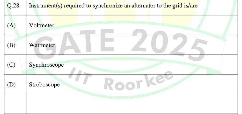
  4. A phase difference of zero, or close to it, at the instant of closing, checked with synchronizing lamps or a synchroscope.

SYNCHRONIZING POWER COEFFICIENT

Per phase, cylindrical rotor, , in W per electrical radian at operating angle . It is the restoring power per unit change in when synchronism is briefly disturbed. Stable operation needs , which is why a cylindrical rotor is limited to .

SYNCHRONIZING TORQUE

in N·m per electrical radian for the 3-phase machine. is per phase and is the synchronous mechanical speed in rad/s.

EXAM TIP

A common trap: an over-excited synchronous motor draws a LEADING current (it looks capacitive to the supply), while an over-excited synchronous generator DELIVERS lagging (inductive) reactive power to the bus. Always decide whether the machine is motoring or generating before assigning the sign of or calling the current leading or lagging.

Starting of Synchronous Motors and Permanent Magnet Synchronous Machines

A synchronous motor is not self-starting. At standstill, the stator field rotating at synchronous speed sweeps past the stationary DC-excited rotor poles. The torque on the rotor alternates in direction at supply frequency, and the rotor's inertia prevents it from following, so the average torque is zero. Practical starting methods bring the rotor close to synchronous speed before it pulls into step: (i) a squirrel-cage damper (amortisseur) winding on the rotor lets the machine start as an induction motor. During this phase the field winding is short-circuited or closed through a resistor, not left open, because a high voltage would otherwise be induced in it. DC excitation is applied near synchronous speed. (ii) An auxiliary pony motor brings the rotor up to speed. (iii) A variable-frequency supply raises the stator frequency from near zero, so the rotor stays in synchronism throughout. The damper winding also damps hunting, the oscillation of the rotor about its steady-state load angle after a sudden change of load or excitation.

A permanent magnet synchronous machine (PMSM), named in the IN syllabus, uses permanent magnets on or inside the rotor in place of a DC field winding. It therefore has no field winding, no slip rings and no field copper loss. The excitation emf is set by the magnet flux and is proportional to speed. It cannot be adjusted through a field current. A surface-mounted PMSM has magnets whose permeability is close to that of air, so it behaves like a round rotor (), and only the excitation (magnet) torque term applies. An interior (buried) magnet PMSM is salient, but in the opposite sense to a wound-field machine. The magnets lie in the d-axis flux path, so usually . The reluctance term therefore changes sign, and the maximum of the total power-angle curve occurs at a load angle above . A PMSM without a cage winding cannot start directly from a fixed-frequency supply. It is either inverter-fed or built as a line-start machine with a rotor cage.

EXAM TIP

On a fixed-voltage, fixed-frequency supply, a PMSM's excitation emf cannot be changed, so the field-current control behind V-curves does not apply. Its power factor is set by the design and the load. In an inverter drive, the d-axis stator current is controlled instead (for example, to weaken the field above base speed).

PREVIOUS-YEAR QUESTIONS

11 questions from the EE papers

Try each question first, then open the answer. One shows the official answer only. We placed each question under a topic ourselves; the exam paper does not label topics.

See these papers in full: GATE EE 2026 · GATE EE 2025 · GATE EE 2024 · GATE EE 2023 · GATE EE 2022 · GATE EE 2020 · GATE EE 2018

GATE 2026 EE Q.20

GATE 2026 · EEQ.20 · 1 mark · MCQ

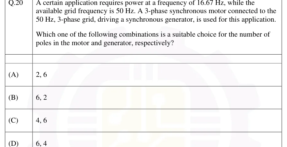
A certain application requires power at a frequency of 16.67 Hz, while the available grid frequency is 50 Hz. A 3-phase synchronous motor connected to the 50 Hz, 3-phase grid, driving a synchronous generator, is used for this application.

Which one of the following combinations is a suitable choice for the number of poles in the motor and generator, respectively?

  1. (A)

    2, 6

  2. (B)

    6, 2

  3. (C)

    4, 6

  4. (D)

    6, 4

Answer and solution
See the question in the paper
GATE 2026 EE Q.20: answer and solution

GATE 2026 EE Q.22

GATE 2026 · EEQ.22 · 1 mark · MCQ

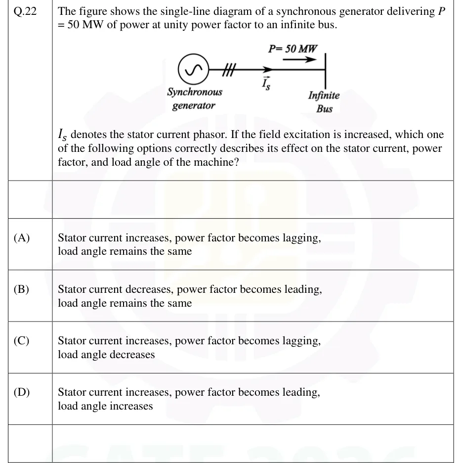
The figure shows the single-line diagram of a synchronous generator delivering P = 50 MW of power at unity power factor to an infinite bus. denotes the stator current phasor. If the field excitation is increased, which one of the following options correctly describes its effect on the stator current, power factor, and load angle of the machine?

GATE 2026 EE question 22: Single-line diagram: a synchronous generator (circle with a sinusoid symbol) connects through a transformer…Tap to open full size
Figure from the GATE 2026 EE paper. It is part of the question.
Figure description

Single-line diagram: a synchronous generator (circle with a sinusoid symbol) connects through a transformer (three-parallel-slash symbol) to a bus bar labelled 'Infinite Bus'. An arrow on the connecting line, labelled I_s, points from the generator toward the bus, indicating the stator current direction. Above the line, an arrow labelled P = 50 MW points from the generator side toward the infinite bus, indicating real power flow into the bus.

  1. (A)

    Stator current increases, power factor becomes lagging, load angle remains the same

  2. (B)

    Stator current decreases, power factor becomes leading, load angle remains the same

  3. (C)

    Stator current increases, power factor becomes lagging, load angle decreases

  4. (D)

    Stator current increases, power factor becomes leading, load angle increases

Answer and solution
GATE 2026 EE Q.22: answer and solution

GATE 2025 EE Q.35

GATE 2025 · EEQ.35 · 1 mark · NAT

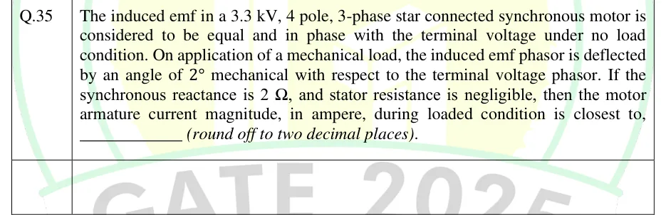
The induced emf in a 3.3 kV, 4 pole, 3-phase star connected synchronous motor is considered to be equal and in phase with the terminal voltage under no load condition. On application of a mechanical load, the induced emf phasor is deflected by an angle of 2° mechanical with respect to the terminal voltage phasor. If the synchronous reactance is 2 Ω, and stator resistance is negligible, then the motor armature current magnitude, in ampere, during loaded condition is closest to, ________ (round off to two decimal places).

Answer and solution
See the question in the paper
GATE 2025 EE Q.35: answer and solution

GATE 2024 EE Q.40

GATE 2024 · EEQ.40 · 2 marks · MCQ

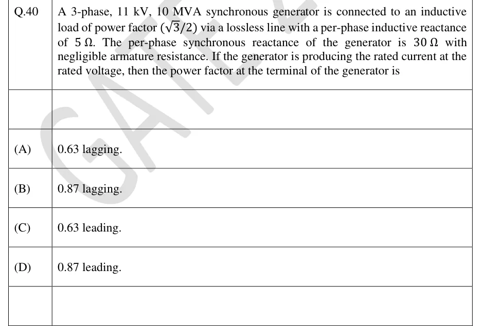
A 3-phase, 11 kV, 10 MVA synchronous generator is connected to an inductive load of power factor () via a lossless line with a per-phase inductive reactance of . The per-phase synchronous reactance of the generator is with negligible armature resistance. If the generator is producing the rated current at the rated voltage, then the power factor at the terminal of the generator is

  1. (A)

    0.63 lagging.

  2. (B)

    0.87 lagging.

  3. (C)

    0.63 leading.

  4. (D)

    0.87 leading.

Answer and solution
See the question in the paper
GATE 2024 EE Q.40: answer and solution

GATE 2022 EE Q.64

GATE 2022 · EEQ.64 · 2 marks · NAT

A star-connected 3-phase, 400 V, 50 kVA, 50 Hz synchronous motor has a synchronous reactance of 1 ohm per phase with negligible armature resistance. The shaft load on the motor is 10 kW while the power factor is 0.8 leading. The loss in the motor is 2 kW. The magnitude of the per phase excitation emf of the motor, in volts, is ________. (round off to nearest integer).

Answer and solution
See the question in the paper
GATE 2022 EE Q.64: answer and solution

GATE 2020 EE Q.7

GATE 2020 · EEQ.7 · 1 mark · MCQ

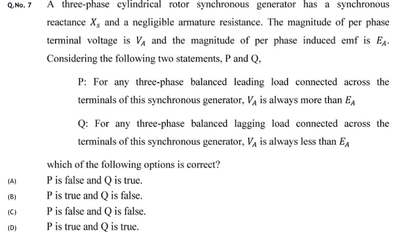
A three-phase cylindrical rotor synchronous generator has a synchronous reactance and a negligible armature resistance. The magnitude of per phase terminal voltage is and the magnitude of per phase induced emf is . Considering the following two statements, P and Q,

P: For any three-phase balanced leading load connected across the terminals of this synchronous generator, is always more than

Q: For any three-phase balanced lagging load connected across the terminals of this synchronous generator, is always less than

which of the following options is correct?

  1. (A)

    P is false and Q is true.

  2. (B)

    P is true and Q is false.

  3. (C)

    P is false and Q is false.

  4. (D)

    P is true and Q is true.

Answer and solution
See the question in the paper
GATE 2020 EE Q.7: answer and solution

GATE 2020 EE Q.43

GATE 2020 · EEQ.43 · 2 marks · MCQ

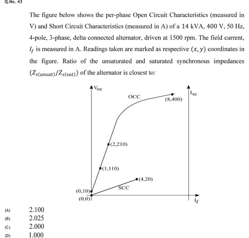
The figure below shows the per-phase Open Circuit Characteristics (measured in V) and Short Circuit Characteristics (measured in A) of a 14 kVA, 400 V, 50 Hz, 4-pole, 3-phase, delta connected alternator, driven at 1500 rpm. The field current, is measured in A. Readings taken are marked as respective coordinates in the figure. Ratio of the unsaturated and saturated synchronous impedances () of the alternator is closest to:

GATE 2020 EE question 43: A graph with horizontal axis I_f (field current, A) and two vertical axes: V_oc (left, open-circuit voltage, V) and I_sc…Tap to open full size
Figure from the GATE 2020 EE paper. It is part of the question.
Figure description

A graph with horizontal axis I_f (field current, A) and two vertical axes: V_oc (left, open-circuit voltage, V) and I_sc (right, short-circuit current, A). Two curves originate from the origin region: (1) OCC — open circuit characteristic, plotted through points (0,10), (1,110), (2,210), rising linearly at first (air-gap line, slope 100 V/A, intercept 10 V — matching residual magnetism) then bending over (saturating) to reach (8,400) at the top right, labelled 'OCC'. (2) SCC — short circuit characteristic, a straight line from (0,0) through (4,20), labelled 'SCC', with much smaller slope (5 A/A), lying below and to the right, not saturating.

  1. (A)

    2.100

  2. (B)

    2.025

  3. (C)

    2.000

  4. (D)

    1.000

Official answer

Official answer: ASource: Official answer key, GATE 2020 EE (IIT Delhi)

GATE 2020 EE Q.43: official answer

GATE 2020 EE Q.49

GATE 2020 · EEQ.49 · 2 marks · NAT

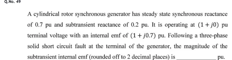
A cylindrical rotor synchronous generator has steady state synchronous reactance of 0.7 pu and subtransient reactance of 0.2 pu. It is operating at pu terminal voltage with an internal emf of pu. Following a three-phase solid short circuit fault at the terminal of the generator, the magnitude of the subtransient internal emf (rounded off to 2 decimal places) is ______ pu.

Answer and solution
See the question in the paper
GATE 2020 EE Q.49: answer and solution

PRACTICE

6 questions to test yourself

PRACTICE 11 mark · NAT

A 3-phase, 4-pole alternator has 36 stator slots carrying a uniformly distributed winding. Find the distribution factor for the fundamental (answer to two decimal places).

Answer and solution

Answer: (accepted range )

  1. Slots per pole , so the slot pitch is electrical.

  2. Slots per pole per phase: .

  3. .

PRACTICE 21 mark · NAT

A 3-phase alternator has 6 poles and is driven so as to generate an emf at a frequency of 50 Hz. What is its synchronous speed in rpm?

Answer and solution

Answer:

  1. Synchronous speed:

  2. rpm

PRACTICE 31 mark · MCQ

For a wound-field (DC-excited) salient-pole synchronous machine, the relation between the direct-axis synchronous reactance and the quadrature-axis synchronous reactance is:

  1. (A)

  2. (B)

  3. (C)

    always

  4. (D)

    and are unrelated to the rotor structure

Answer and solution

Answer: (A)

  1. The d-axis lies along the pole axis, where the air gap under the pole face is small. Its magnetic path has low reluctance and high permeance.

  2. The q-axis lies in the inter-polar region, where the effective air gap is large. Its path has high reluctance and low permeance.

  3. Reactance is proportional to inductance, and inductance is proportional to permeance. The d-axis path therefore gives the larger reactance: .

  4. For a cylindrical (round) rotor, the air gap is the same on both axes, so . That is the special case, not the salient-pole result.

PRACTICE 42 marks · NAT

A 3-phase, star-connected cylindrical-rotor alternator has a per-phase terminal voltage of 230 V and delivers a full-load current of 20 A at 0.8 pf lagging. The per-phase synchronous reactance is 5 Ω and armature resistance is negligible. Calculate the percentage voltage regulation (in %) by the EMF (synchronous impedance) method.

Answer and solution

Answer: (accepted range )

  1. Take as the reference: V. With lagging, , so A.

  2. With : , and V.

  3. V.

  4. V.

  5. Percentage regulation .

PRACTICE 52 marks · MSQ

For the power-angle characteristic of a wound-field salient-pole synchronous generator connected to an infinite bus of voltage , with excitation emf , load angle , direct-axis reactance and quadrature-axis reactance (armature resistance neglected), which of the following statements are correct?

  1. (A)

    The reluctance power term is present even when the field current (and hence ) is zero

  2. (B)

    The reluctance power term varies with load angle as

  3. (C)

    Maximum power always occurs exactly at

  4. (D)

    for this machine

Answer and solution

Answer: (A), (B)

  1. The salient-pole power-angle relation is .

  2. The second (reluctance power) term depends only on , , and , not on . It is therefore present even when there is no field excitation (). A is TRUE.

  3. The reluctance term varies as . B is TRUE.

  4. . At this equals , so is already falling and its maximum lies below . C is FALSE; C holds only for a round rotor, where .

  5. In a wound-field salient-pole machine . D is FALSE.

  6. The correct statements are A and B.

PRACTICE 61 mark · MCQ

A 3-phase synchronous motor is connected directly to a balanced supply with its field winding excited from a separate DC source, and the rotor is at standstill. Which of the following correctly explains why the motor fails to develop a net starting torque under these conditions?

  1. (A)

    The rotating stator field sweeps past the stationary rotor poles, producing equal forward and reverse torque pulses each cycle that average to zero net torque

  2. (B)

    The armature resistance is too high at standstill for any current to flow

  3. (C)

    The synchronous reactance becomes infinite at zero speed

  4. (D)

    The DC field excitation opposes the stator field at all times, giving a constant negative torque

Answer and solution

Answer: (A)

  1. The balanced 3-phase stator currents produce a magnetic field that rotates at synchronous speed .

  2. At standstill the rotor and its DC-excited poles are stationary, so the rotating stator field repeatedly moves into and out of alignment with the rotor poles.

  3. The torque on the rotor therefore reverses direction every half-cycle of this relative motion. Because of its inertia, the rotor cannot accelerate enough within one half-cycle to follow the field.

  4. The forward and backward torque pulses average to zero, so there is no net starting torque. The motor needs an auxiliary means of starting, such as a damper (cage) winding, a pony motor or a variable-frequency supply.

OFFICIAL GATE 2027 SYLLABUS WORDING

Copied from the GATE 2027 syllabus; see all 2027 syllabi.

GATE EE

Synchronous machines: cylindrical and salient pole machines, performance and characteristics, regulation and parallel operation of generators, starting of synchronous motors

GATE IN

permanent magnet synchronous machines

Preparing in Kolkata? IAE Academy's course for GATE EE or GATE IN.