IAE Academy

IN THE EE SYLLABUS

Three-phase and single-phase induction machines

Study notes for GATE EE, Electrical Machines: three-phase and single-phase induction machines. They cover the rotating magnetic field and principle of operation, slip and rotor frequency, and the per-phase equivalent circuit (exact and approximate). Also covered: power flow (the 1 : s : (1-s) split, losses and efficiency) and the torque-slip relations (general, starting and maximum torque, slip at maximum torque, the T/T_max ratio form, and the operating regions). Then the no-load and blocked-rotor tests, starting methods (DOL, star-delta, autotransformer, rotor resistance) with their current and torque ratios, and speed control (stator voltage, V/f and field weakening, pole changing, rotor resistance, slip-power recovery). The last section is the double-revolving-field explanation of the single-phase induction motor. Six original GATE-style practice questions (MCQ, MSQ, NAT) with worked steps.

17 previous-year questions · 17 solved · 6 practice questions

Rotating Magnetic Field and Principle of Operation

The stator has three phase windings displaced 120° electrical in space. When it carries balanced three-phase currents (120° apart in time), it produces an air-gap field of constant magnitude that rotates at synchronous speed . This field sweeps past the rotor conductors and induces emfs and currents in them. Those rotor currents interact with the air-gap field to produce torque, which drags the rotor in the direction of the field. When the machine runs as a motor, the rotor always turns below synchronous speed: at synchronous speed there would be no relative motion, so no induced rotor emf, no rotor current and no torque. This is why it is called an asynchronous or induction machine.

SYNCHRONOUS SPEED (RPM)

= supply frequency (Hz), = number of poles. This is the speed of the rotating stator field. In rad/s: .

AMPLITUDE OF THE RESULTANT ROTATING MMF (THREE-PHASE)

is the peak MMF of one phase winding. Holds for a balanced three-phase winding carrying balanced three-phase currents. The resultant has constant amplitude and rotates at .

The rotor currents are at frequency , so the field they set up rotates at relative to the rotor. The rotor itself turns at , so the rotor field rotates at relative to the stator. The stator and rotor fields are therefore stationary relative to each other at every speed, which is what lets the machine develop a steady torque.

Types of three-phase induction motors

  1. Squirrel-cage rotor: rotor bars short-circuited by end rings. The rotor resistance is fixed and no external rotor connection is possible. The construction is simple and rugged.

  2. Deep-bar and double-cage rotors: squirrel-cage variants whose effective rotor resistance is high at standstill (rotor frequency ) and low near synchronous speed (rotor frequency ). This gives a higher starting torque without a large running slip.

  3. Slip-ring (wound-rotor) motor: the three-phase rotor winding is brought out to slip rings, so external resistance (or a converter) can be connected in the rotor circuit to improve starting torque or control speed.

EXAM TIP

To reverse a three-phase induction motor, interchange any two of the three stator supply leads. This reverses the phase sequence and hence the direction of the rotating field.

Slip and Rotor Frequency

Slip measures how far the rotor speed lags the rotating field. Convention used throughout: is the synchronous speed and the rotor speed, both in the same units, and slip is a fraction. The slip speed is .

SLIP

Dimensionless. at standstill and near synchronous speed. : motoring. : the rotor is driven above (induction generator). : the rotor turns against the field (braking, as in plugging).

ROTOR (INDUCED) FREQUENCY

Frequency of the currents induced in the rotor at slip , where is the stator supply frequency. At standstill (), .

ROTOR EMF AND ROTOR LEAKAGE REACTANCE AT SLIP $S$

and are the per-phase rotor emf and leakage reactance at standstill (). Both scale with slip because they are proportional to the rotor frequency . The rotor resistance does not depend on slip (skin effect in deep-bar and double-cage rotors ignored).

Per-Phase Equivalent Circuit

At slip the rotor circuit has emf and impedance , at frequency . Dividing the rotor emf and impedance by gives the same rotor current from acting on , now at stator frequency. After referral to the stator through the turns ratio (as in a transformer), this gives the standard per-phase equivalent circuit used for all calculations. All quantities are per phase and referred to the stator.

Per-phase equivalent circuit elements (all referred to the stator)

Symbol

Meaning

Stator winding resistance and leakage reactance

Magnetizing reactance (shunt branch). Core loss is represented by a resistance in parallel with it, or lumped with rotational loss

Rotor resistance and standstill leakage reactance referred to the stator

Slip-dependent rotor branch resistance. It accounts for rotor copper loss and mechanical power together

Applied per-phase stator voltage ( for a star-connected stator)

SPLIT OF THE ROTOR BRANCH RESISTANCE

The fixed part dissipates rotor copper loss. The slip-dependent part is the equivalent load resistance, and the power it absorbs is the gross mechanical power developed, per phase.

The torque formulas below use the approximate equivalent circuit, in which the magnetizing branch is moved to the stator terminals. The rotor current then flows through , , and in series. With the exact circuit (magnetizing branch between the stator and rotor impedances), replace , and in these formulas with the Thevenin voltage, resistance and reactance seen from the rotor branch.

ROTOR CURRENT REFERRED TO THE STATOR (APPROXIMATE CIRCUIT)

Per-phase rms rotor current, with the per-phase voltage. The stator current is the phasor sum of and the no-load (magnetizing) current.

Power Flow, Efficiency and Torque-Slip Characteristic

Power flow (motoring)

  1. Input: .

  2. Subtract stator copper loss and core loss. What remains crosses the air gap: the air-gap power .

  3. Rotor copper loss: .

  4. Gross mechanical power developed: .

  5. Subtract rotational (friction and windage) loss, and stray loss if given, to get the shaft output .

  6. Efficiency: .

AIR-GAP POWER SPLIT

is the total air-gap power, the total rotor copper loss and the gross mechanical power. The split gives rotor power quantities without computing currents. Since , the motor's overall efficiency cannot exceed .

DEVELOPED (ELECTROMAGNETIC) TORQUE

is the total three-phase air-gap power and the synchronous speed in rad/s. is the rotor speed in rad/s. Divide air-gap power by synchronous speed, or mechanical power by rotor speed, and never mix the two. Shaft torque is lower by the rotational-loss torque.

TORQUE IN TERMS OF APPLIED VOLTAGE

Approximate equivalent circuit. is the per-phase stator voltage. For the exact circuit use the Thevenin values in place of .

SLIP AT MAXIMUM TORQUE

Approximate equivalent circuit. Independent of the applied voltage and proportional to . Adding rotor resistance moves the maximum-torque point towards standstill.

MAXIMUM (PULL-OUT OR BREAKDOWN) TORQUE

Approximate equivalent circuit. Independent of : changing the rotor resistance moves where the maximum torque occurs, not its value. Proportional to .

STARTING TORQUE ($S=1$)

The general torque expression with .

TORQUE RELATIVE TO MAXIMUM TORQUE

Valid when the stator resistance is neglected (), so that . The same supply voltage and frequency apply to and .

Shape of the torque-slip curve (with neglected): at small slip (), , so torque rises roughly in proportion to slip and speed falls almost linearly with load. At large slip (), torque falls roughly as . For a constant-torque load, stable operation is on the low-slip side, , where torque rises as speed falls.

EXAM TIP

At a fixed slip, torque is proportional to while the current is only proportional to . A voltage dip, or a reduced-voltage starter, therefore cuts the torque by the square of the voltage ratio.

No-Load and Blocked-Rotor Tests

No-load test

  1. The motor runs unloaded at rated voltage and frequency. Measure the input voltage, current and total power.

  2. Slip is very small, so is very large and the rotor branch draws negligible current. The input current is mostly magnetizing current, so the measured power factor is low and lagging.

  3. Input power minus the small stator copper loss at this current gives core loss plus rotational (friction and windage) loss.

  4. Used to find the magnetizing branch (mainly ) and the combined no-load loss.

QUANTITIES FROM THE NO-LOAD TEST

and are line values and is the total three-phase input power. Per-phase values are taken for an equivalent star connection. The second relation uses the low power factor (impedance almost entirely reactive).

Blocked-rotor test

  1. The rotor is locked () and a reduced voltage is applied so that rated (or a specified) current flows. Full voltage at standstill would draw several times rated current.

  2. Measure the applied voltage, current and input power at this reduced voltage.

  3. At standstill the series branch is much smaller than , and the reduced voltage makes the magnetizing current small. The measured impedance is therefore essentially the series leakage impedance.

  4. This gives (from the power) and (from the impedance triangle), both referred to the stator. is found separately (for example by a DC test), which isolates .

PARAMETERS FROM THE BLOCKED-ROTOR TEST

and are line values and is the total three-phase input power. Results are per phase for an equivalent star connection. If the test is run at a reduced frequency , multiply the reactance by . The test cannot separate from , so a split (often equal) must be assumed or given.

Starting Methods

At standstill (), the rotor-branch resistance in the equivalent circuit is at its smallest value, . The total impedance is therefore at its lowest, and started direct-on-line the motor draws several times its rated current (how many depends on the design). Each starting method trades starting current against starting torque.

Common starting methods (squirrel-cage unless noted)

  1. Direct-on-line (DOL): full line voltage is applied at once. Simplest, but it draws the full-voltage starting current and gives the full-voltage starting torque .

  2. Star-delta starter (for motors designed to run in delta): the winding is connected in star to start, then switched to delta. In star each phase gets , so the phase current is of its DOL value. With DOL in delta, the line current is times the phase current, so the line starting current falls to of its DOL value. Starting torque also falls to , because .

  3. Autotransformer starter: the motor is fed at a fraction of line voltage. Motor current is times its DOL value, the supply-line current times, and starting torque times (ideal autotransformer, magnetizing current neglected). Star-delta behaves like the case .

  4. Rotor resistance starter (wound-rotor motors only): external rotor resistance limits the starting current and moves towards . Unlike the reduced-voltage methods, it can raise the starting torque while also limiting the current. The resistance is cut out in steps as the motor speeds up.

Comparison with DOL (squirrel-cage methods, magnetizing current neglected)

Method

Supply-line starting current vs DOL

Starting torque vs DOL

DOL

1

1

Star-delta

1/3

1/3

Autotransformer (tap ratio )

STARTING TORQUE RELATIVE TO FULL-LOAD TORQUE

From with constant and the magnetizing current neglected. is the DOL (full-voltage) starting current, the full-load current, the full-load slip. for DOL, for star-delta, and = tap ratio for an autotransformer.

ROTOR RESISTANCE FOR MAXIMUM STARTING TORQUE

Wound-rotor motor, approximate equivalent circuit. is the added rotor resistance referred to the stator. This choice makes .

Speed Control

Since , speed can be changed through the slip (stator voltage, rotor resistance, slip-power recovery), the frequency , or the number of poles .

Speed control methods

  1. Stator voltage control: torque at each slip falls as , so a given load settles at a higher slip and lower speed. The useful range is narrow, because stable operation must stay on the low-slip side of . Efficiency is poor at low speed, since rotor copper loss grows with slip.

  2. V/f control (variable voltage, variable frequency) below base speed: voltage and frequency are changed in the same ratio, keeping the air-gap flux nearly constant. changes with frequency, so the torque-speed curve shifts along the speed axis, giving a wide and efficient speed range. At low frequency the stator resistance drop becomes significant, and extra voltage (voltage boost) is needed to hold the flux.

  3. Above base speed: the voltage is held at its rated value while frequency rises, so the flux falls (field weakening) and the maximum torque falls roughly as (stator resistance neglected).

  4. Pole changing: the stator winding is reconnected to change the number of poles , giving a few discrete synchronous speeds. Used with squirrel-cage rotors, which adapt to any pole number.

  5. Rotor resistance control (wound-rotor only): extra rotor resistance raises the operating slip at a given torque and lowers the speed. It is simple but wasteful, because the slip power is lost as loss in the added resistance.

  6. Slip-power recovery (wound-rotor only): instead of being wasted in resistors, the rotor slip-frequency power is converted and returned to the supply (or to the shaft), giving speed control below synchronous speed with better efficiency.

EXAM TIP

With constant flux (constant , or constant with the stator resistance drop neglected), the maximum torque stays the same at every frequency below base speed. Plain stator-voltage reduction, by contrast, cuts the maximum torque as .

Single-Phase Induction Motor: Operating Principle

A single-phase winding carrying alternating current produces a pulsating field: its axis is fixed in space and its magnitude varies sinusoidally with time. It is not a rotating field. On its own it gives zero net torque at standstill, so a single-phase induction motor is not self-starting. An auxiliary arrangement (an auxiliary winding with a series resistance or capacitor, or a shaded pole) is needed to start it. Once the rotor is turning, the motor keeps running and developing torque on the main winding alone.

The double-revolving-field theory explains this. A pulsating field of peak amplitude is equivalent to two fields of amplitude each, rotating at synchronous speed in opposite directions. At standstill both have slip 1 and produce equal and opposite torques, so the net starting torque is zero.

RESOLUTION OF THE PULSATING FIELD (DOUBLE-REVOLVING-FIELD THEORY)

is the electrical angle around the air gap, measured from the winding axis. The first term is a forward field of amplitude rotating in the direction. The second is a backward field of the same amplitude rotating in the direction. Both rotate at synchronous speed.

SLIPS RELATIVE TO THE FORWARD AND BACKWARD FIELDS

is the rotor speed in the forward direction. At standstill and , so the net torque .

Once the rotor turns in some direction, the slip relative to the field rotating that way drops below 1, and the slip relative to the opposite field rises above 1 (towards 2). The field rotating with the rotor then gives more torque than the other opposes, so a net torque acts in the direction of rotation and the motor accelerates in that direction.

Starting arrangements (operating principle)

  1. Split-phase (resistance-start): an auxiliary winding with a higher resistance-to-reactance ratio than the main winding. Its current is phase-shifted from the main current, which gives a starting field that is partly rotating. It is usually disconnected by a centrifugal switch once the motor is running.

  2. Capacitor-start: a capacitor in series with the auxiliary winding brings the phase difference closer to 90°, giving a higher starting torque.

  3. Capacitor-start capacitor-run, and permanent-split capacitor: the auxiliary winding (with its capacitor) stays in circuit while running, which improves running performance.

  4. Shaded-pole: a short-circuited copper ring on part of each pole delays the flux in the shaded part, giving a small starting torque towards the shaded portion.

EXAM TIP

Running on the main winding alone, a single-phase induction motor keeps turning in whichever direction it is already going. The direction it starts in is set by the auxiliary winding: reverse either the auxiliary or the main winding connections to reverse it. In a shaded-pole motor, the position of the shading ring sets the direction. A three-phase motor's direction is set by the phase sequence.

PREVIOUS-YEAR QUESTIONS

17 questions from the EE and IN papers

Try each question first, then open the answer. We placed each question under a topic ourselves; the exam paper does not label topics.

See these papers in full: GATE EE 2026 · GATE EE 2025 · GATE EE 2024 · GATE EE 2023 · GATE EE 2022 · GATE EE 2020 · GATE EE 2018 · GATE IN 2025 · GATE IN 2024 · GATE IN 2022

GATE 2026 EE Q.21

GATE 2026 · EEQ.21 · 1 mark · MCQ

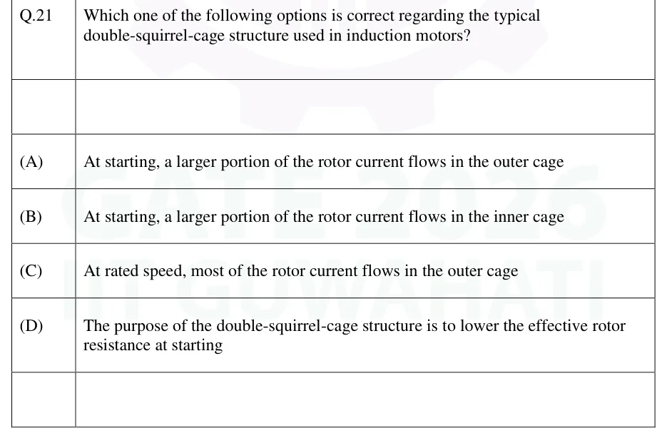
Which one of the following options is correct regarding the typical double-squirrel-cage structure used in induction motors?

  1. (A)

    At starting, a larger portion of the rotor current flows in the outer cage

  2. (B)

    At starting, a larger portion of the rotor current flows in the inner cage

  3. (C)

    At rated speed, most of the rotor current flows in the outer cage

  4. (D)

    The purpose of the double-squirrel-cage structure is to lower the effective rotor resistance at starting
Answer and solution
See the question in the paper
GATE 2026 EE Q.21: answer and solution

GATE 2026 EE Q.59

GATE 2026 · EEQ.59 · 2 marks · NAT

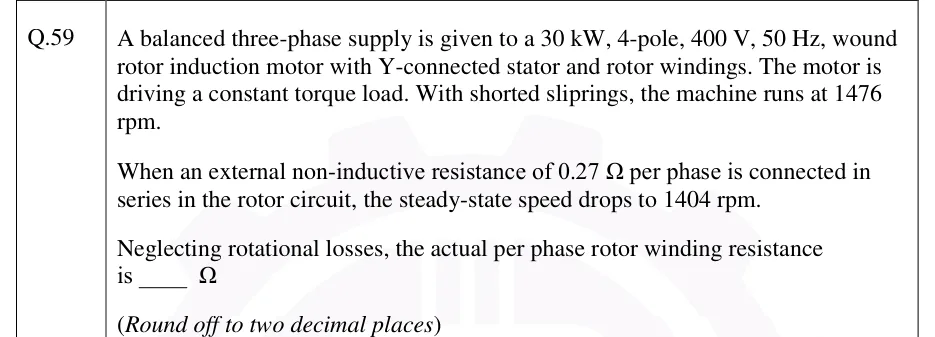
A balanced three-phase supply is given to a 30 kW, 4-pole, 400 V, 50 Hz, wound rotor induction motor with Y-connected stator and rotor windings. The motor is driving a constant torque load. With shorted sliprings, the machine runs at 1476 rpm.

When an external non-inductive resistance of 0.27 Ω per phase is connected in series in the rotor circuit, the steady-state speed drops to 1404 rpm.

Neglecting rotational losses, the actual per phase rotor winding resistance is _____ Ω

(Round off to two decimal places)

Answer and solution
See the question in the paper
GATE 2026 EE Q.59: answer and solution

GATE 2025 EE Q.26

GATE 2025 · EEQ.26 · 1 mark · MCQ

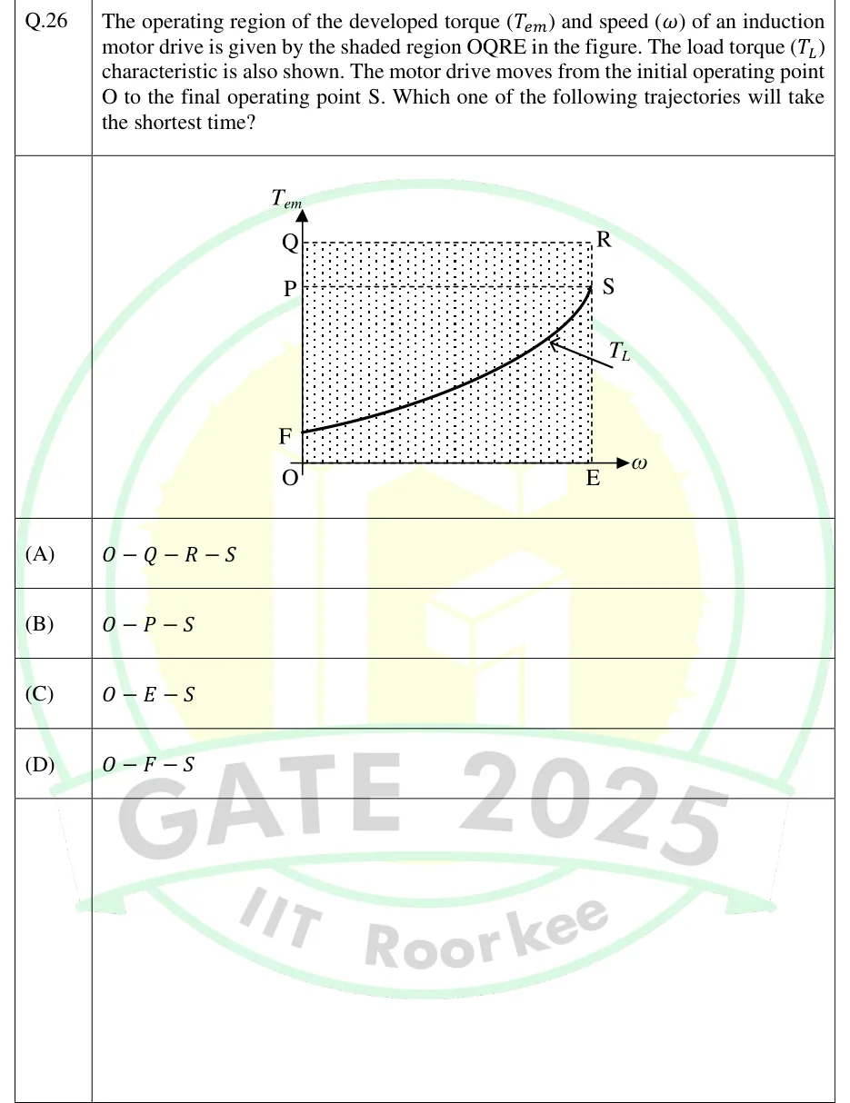
The operating region of the developed torque () and speed () of an induction motor drive is given by the shaded region OQRE in the figure. The load torque () characteristic is also shown. The motor drive moves from the initial operating point O to the final operating point S. Which one of the following trajectories will take the shortest time?

GATE 2025 EE question 26: A T_em (vertical axis) vs ω (horizontal axis) plot, origin at O.Tap to open full size
Figure from the GATE 2025 EE paper. It is part of the question.
Figure description

A T_em (vertical axis) vs ω (horizontal axis) plot, origin at O. A shaded (dotted) rectangular region OQRE is bounded by: the vertical axis from O to Q (torque axis, at ω =0), the horizontal top line from Q to R (at torque level T_Q, the maximum torque), the vertical line from R down to E (at speed ω_E, the maximum speed shown), and the horizontal axis from E back to O. Point P lies on the vertical torque axis (segment OQ) below Q, marking an intermediate torque level; a dashed horizontal line runs from P across to point S. Point F lies on the vertical torque axis below P, near the bottom, marking a lower/starting torque level. A smooth monotonically increasing curve, labelled T_L (the load torque characteristic), starts at point F (on the torque axis, ω =0) and rises with increasing slope (convex, fan/quadratic-like shape) as ω increases, passing below Q and R, and terminating at point S, which lies at the top-right of the shaded region directly below R (i.e., S is at ω = ω_E, at a torque level equal to that of the dashed line from P — below T_Q). The four candidate trajectories from O to S are drawn as straight-line paths: O to Q to R to S (up the torque axis, across the top, then down to S); O to P to S (up the torque axis to P, then diagonally to S); O to E to S (along the speed axis to E, then straight up to S); O to F to S (up the torque axis to F, then along/near the T_L curve to S).

  1. (A)

  2. (B)

  3. (C)

  4. (D)

Answer and solution
GATE 2025 EE Q.26: answer and solution

GATE 2025 EE Q.45

GATE 2025 · EEQ.45 · 2 marks · MCQ

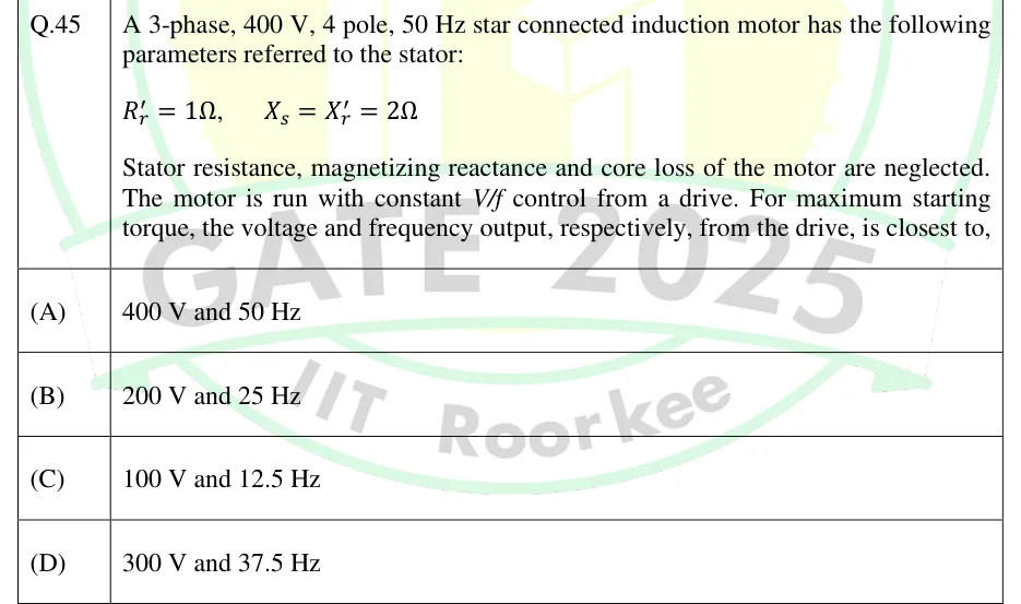
A 3-phase, 400 V, 4 pole, 50 Hz star connected induction motor has the following parameters referred to the stator: , . Stator resistance, magnetizing reactance and core loss of the motor are neglected. The motor is run with constant V/f control from a drive. For maximum starting torque, the voltage and frequency output, respectively, from the drive, is closest to,

  1. (A)

    400 V and 50 Hz

  2. (B)

    200 V and 25 Hz

  3. (C)

    100 V and 12.5 Hz

  4. (D)

    300 V and 37.5 Hz

Answer and solution
See the question in the paper
GATE 2025 EE Q.45: answer and solution

GATE 2025 IN Q.46

GATE 2025 · INQ.46 · 2 marks · MCQ

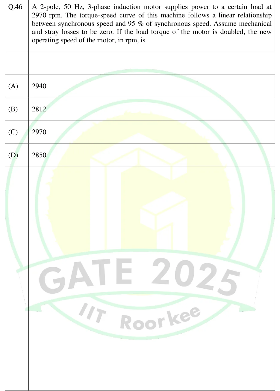
A 2-pole, 50 Hz, 3-phase induction motor supplies power to a certain load at 2970 rpm. The torque-speed curve of this machine follows a linear relationship between synchronous speed and 95% of synchronous speed. Assume mechanical and stray losses to be zero. If the load torque of the motor is doubled, the new operating speed of the motor, in rpm, is

  1. (A)

    2940

  2. (B)

    2812

  3. (C)

    2970

  4. (D)

    2850

Answer and solution
See the question in the paper
GATE 2025 IN Q.46: answer and solution

GATE 2024 EE Q.54

GATE 2024 · EEQ.54 · 2 marks · NAT

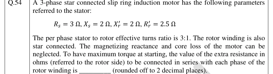
A 3-phase star connected slip ring induction motor has the following parameters referred to the stator: , , , . The per phase stator to rotor effective turns ratio is 3:1. The rotor winding is also star connected. The magnetizing reactance and core loss of the motor can be neglected. To have maximum torque at starting, the value of the extra resistance in ohms (referred to the rotor side) to be connected in series with each phase of the rotor winding is ________ (rounded off to 2 decimal places).

Answer and solution
See the question in the paper
GATE 2024 EE Q.54: answer and solution

GATE 2023 EE Q.15

GATE 2023 · EEQ.15 · 1 mark · MCQ

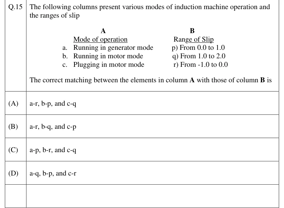
The following columns present various modes of induction machine operation and the ranges of slip.

Column A (Mode of operation): a. Running in generator mode b. Running in motor mode c. Plugging in motor mode
Column B (Range of Slip): p) From 0.0 to 1.0 q) From 1.0 to 2.0 r) From -1.0 to 0.0

The correct matching between the elements in column A with those of column B is

  1. (A)

    a-r, b-p, and c-q

  2. (B)

    a-r, b-q, and c-p

  3. (C)

    a-p, b-r, and c-q

  4. (D)

    a-q, b-p, and c-r

Answer and solution
See the question in the paper
GATE 2023 EE Q.15: answer and solution

GATE 2023 EE Q.48

GATE 2023 · EEQ.48 · 2 marks · NAT

A three phase 415 V, 50 Hz, 6-pole, 960 RPM, 4 HP squirrel cage induction motor drives a constant torque load at rated speed operating from rated supply and delivering rated output. If the supply voltage and frequency are reduced by 20%, the resultant speed of the motor in RPM (neglecting the stator leakage impedance and rotational losses) is __________ (Round off to the nearest integer).

Answer and solution
See the question in the paper
GATE 2023 EE Q.48: answer and solution

GATE 2022 EE Q.63

GATE 2022 · EEQ.63 · 2 marks · NAT

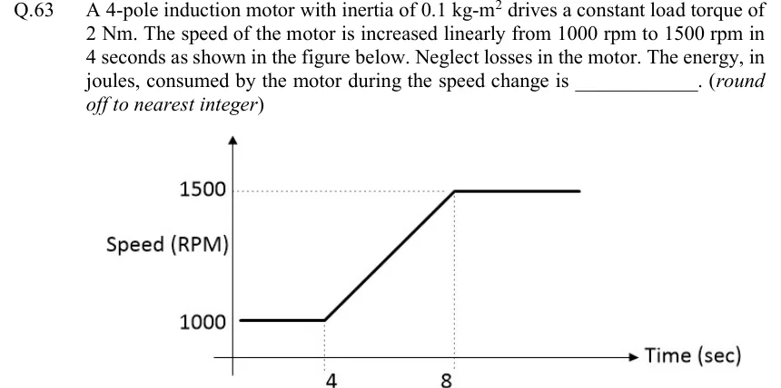
A 4-pole induction motor with inertia of drives a constant load torque of . The speed of the motor is increased linearly from to in seconds as shown in the figure below. Neglect losses in the motor. The energy, in joules, consumed by the motor during the speed change is ______. (round off to nearest integer)

GATE 2022 EE question 63: A speed-vs-time graph.Tap to open full size
Figure from the GATE 2022 EE paper. It is part of the question.
Figure description

A speed-vs-time graph. Y-axis: 'Speed (RPM)', with marked values 1000 and 1500 (dotted horizontal guide lines at these levels). X-axis: 'Time (sec)', with marked values 4 and 8 (dotted vertical guide lines at these points). The curve is flat at 1000 rpm from t=0 to t=4, then rises linearly from 1000 rpm at t=4 to 1500 rpm at t=8, then remains flat at 1500 rpm for t>8.

Answer and solution
GATE 2022 EE Q.63: answer and solution

GATE 2022 EE Q.65

GATE 2022 · EEQ.65 · 2 marks · NAT

A 3-phase, 415 V, 4-pole, 50 Hz induction motor draws 5 times the rated current at rated voltage at starting. It is required to bring down the starting current from the supply to 2 times of the rated current using a 3-phase autotransformer. If the magnetizing impedance of the induction motor and no load current of the autotransformer is neglected, then the transformation ratio of the autotransformer is given by ________. (round off to two decimal places).

Answer and solution
See the question in the paper
GATE 2022 EE Q.65: answer and solution

GATE 2018 EE Q.54

GATE 2018 · EEQ.54 · 2 marks · NAT

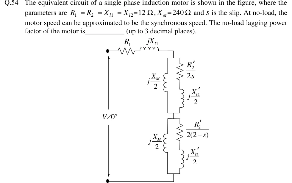
The equivalent circuit of a single phase induction motor is shown in the figure, where the parameters are , and is the slip. At no-load, the motor speed can be approximated to be the synchronous speed. The no-load lagging power factor of the motor is____________ (up to 3 decimal places).

GATE 2018 EE question 54: Single-phase induction motor per-phase equivalent circuit (double revolving field model).Tap to open full size
Figure from the GATE 2018 EE paper. It is part of the question.
Figure description

Single-phase induction motor per-phase equivalent circuit (double revolving field model). Source: a voltage source V ∠ 0° on the left, with an arrow showing current flowing up into the circuit from its top terminal. In series from the top terminal: stator resistance R_1, then stator leakage reactance jX_l1. This series combination connects to two impedance blocks stacked in series (top block = forward field, bottom block = backward field), which then return to the bottom terminal of the source. Top (forward) block: a parallel combination of (a) j(X_M)/(2) (magnetizing branch) and (b) a series branch of (R_2')/(2s) and j X_l2'2. Bottom (backward) block: a parallel combination of (a) j(X_M)/(2) and (b) a series branch of (R_2')/(2(2-s)) and j X_l2'2. All parallel branches drawn as ladder rungs between the top node (junction of the two blocks) / outer rails and the bottom rail leading back to the source.

Answer and solution
GATE 2018 EE Q.54: answer and solution

PRACTICE

6 questions to test yourself

PRACTICE 11 mark · MCQ

A 4-pole, 50 Hz, three-phase induction motor runs at a slip of 0.04. The rotor speed, in rpm, is closest to

  1. (A)

    1440

  2. (B)

    1500

  3. (C)

    1460

  4. (D)

    1380

Answer and solution

Answer: (A)

  1. Synchronous speed: rpm.

  2. Rotor speed: rpm.

PRACTICE 22 marks · NAT

A three-phase induction motor is represented by its approximate per-phase equivalent circuit (magnetizing branch at the stator terminals). The rotor resistance referred to the stator is per phase, and the total leakage reactance referred to the stator is per phase. The stator resistance is negligible. The slip at which the developed torque is maximum is ______.

Answer and solution

Answer: (accepted range )

  1. For the approximate equivalent circuit: .

  2. With : .

PRACTICE 32 marks · MSQ

Which of the following statements about the no-load test and the blocked-rotor test on a three-phase induction motor are correct?

  1. (A)

    The no-load input power, after subtracting the stator copper loss, approximates the sum of core loss and rotational (friction and windage) loss.

  2. (B)

    The blocked-rotor test is carried out at the rated line voltage with the rotor locked.

  3. (C)

    The blocked-rotor test gives the total per-phase leakage reactance referred to the stator (at the test frequency).

  4. (D)

    The power factor measured in the no-load test is low and lagging, because the no-load current is mostly magnetizing current.

Answer and solution

Answer: (A), (C), (D)

  1. No-load: , so is very large and the rotor branch carries negligible current. Input power minus the stator copper loss is core loss plus rotational loss. A is correct.

  2. The no-load current is mostly magnetizing current, so the measured power factor is low and lagging. D is correct.

  3. The blocked-rotor test uses a reduced voltage, chosen so that about rated current flows. Rated voltage at standstill would draw several times rated current. B is incorrect.

  4. At standstill the series branch is much smaller than , so the measured impedance is essentially referred to the stator, at the test frequency. C is correct.

PRACTICE 41 mark · MCQ

An induction motor operates at slip . If is the total air-gap power and is the gross mechanical power developed, then equals

  1. (A)

  2. (B)

  3. (C)

  4. (D)

Answer and solution

Answer: (B)

  1. The air-gap power splits as , where is the rotor copper loss.

  2. Hence .

PRACTICE 52 marks · NAT

A three-phase, 4-pole, 50 Hz induction motor runs at a slip of 0.05. Its total air-gap power (all three phases) is 6 kW. Friction and windage loss is 150 W; neglect stray losses. The shaft (output) torque, in N·m, is ______.

Answer and solution

Answer: (accepted range )

  1. rpm, so rpm and rad/s.

  2. Gross mechanical power: W.

  3. Shaft output: W.

  4. Shaft torque: N·m.

  5. Check: the developed torque is N·m. The friction-and-windage torque is N·m, and N·m.

PRACTICE 62 marks · NAT

A three-phase squirrel-cage induction motor draws a starting current of 6 times its full-load current when started direct-on-line, and its full-load slip is 0.04. It is started through an autotransformer that applies 60% of rated voltage to the motor. Neglecting the magnetizing current and assuming constant rotor resistance, the starting torque as a fraction of the full-load torque is ______.

Answer and solution

Answer: (accepted range )

  1. Torque , so , where is the motor current at start.

  2. With the autotransformer, the motor current at start is .

  3. .

OFFICIAL GATE 2027 SYLLABUS WORDING

Copied from the GATE 2027 syllabus; see all 2027 syllabi.

GATE EE

Three-phase induction machines: principle of operation, types, performance, torque-speed characteristics, no-load and blocked-rotor tests, equivalent circuit, starting and speed control; Operating principle of single-phase induction motors

Preparing in Kolkata? IAE Academy's course for GATE EE.