
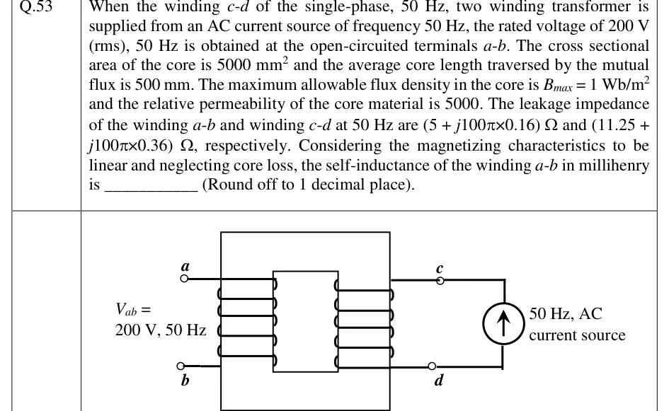
(NAT, 2 marks) When the winding c-d of the single-phase, 50 Hz, two winding transformer is supplied from an AC current source of frequency 50 Hz, the rated voltage of 200 V (rms), 50 Hz is obtained at the open-circuited terminals a-b. The cross sectional area of the core is 5000 mm^2 and the average core length traversed by the mutual flux is 500 mm. The maximum allowable flux density in the core is B_max = 1 Wb/m^2 and the relative permeability of the core material is 5000. The leakage impedance of the winding a-b and winding c-d at 50 Hz are (5 + j100π×0.16) Ω and (11.25 + j100π×0.36) Ω, respectively. Considering the magnetizing characteristics to be linear and neglecting core loss, the self-inductance of the winding a-b in millihenry is ______ (Round off to 1 decimal place).
 Tap to open full size
Figure description
A single-phase two-winding transformer schematic. A rectangular core window is drawn with two vertical windings side by side sharing the same magnetic core (a large outer rectangle representing the core, with an inner vertical divider). The left winding is labelled with terminals a (top) and b (bottom), open-circuited, with the annotation 'V_ab = 200 V, 50 Hz' written beside it (this is the induced open-circuit voltage, not an applied source). The right winding is labelled with terminals c (top) and d (bottom); c and d are connected externally to an AC current source, drawn as a circle with an upward arrow inside it, labelled '50 Hz, AC current source'. Both windings are drawn as coils wound on the same core limb region (mutually coupled), with small circles at each winding's terminals denoting the winding ends a, b, c, d.