
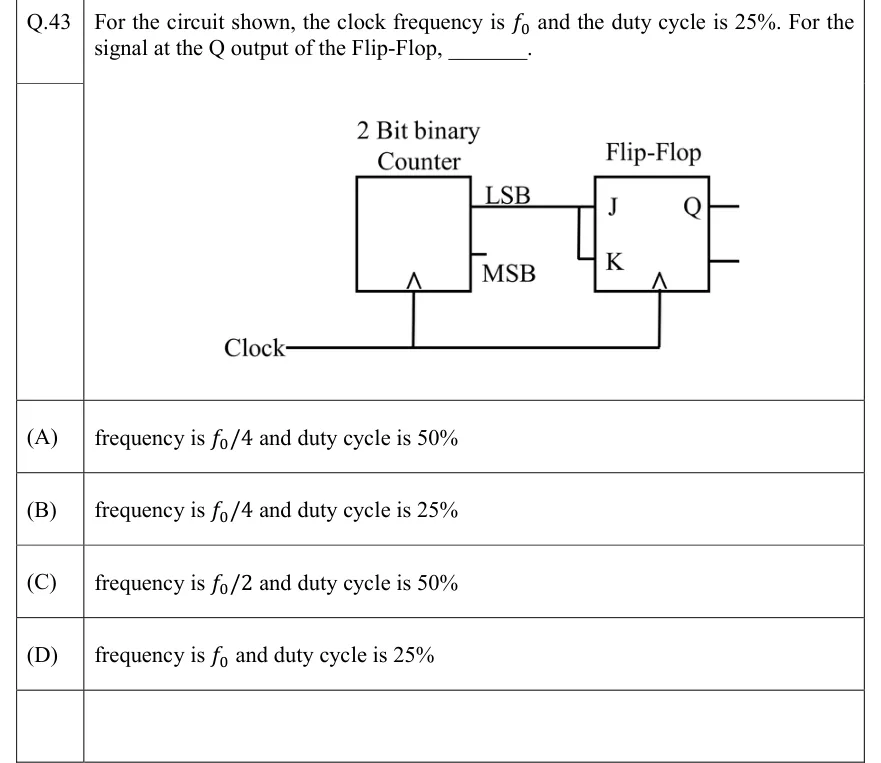
For the circuit shown, the clock frequency is and the duty cycle is 25%. For the signal at the Q output of the Flip-Flop, ________.
 Tap to open full size
Figure description
A block labelled '2 Bit binary Counter' has two outputs on its right side: LSB (upper) and MSB (lower). The MSB output is a short stub that connects to nothing. The LSB output runs to the J input of a block labelled 'Flip-Flop' (a JK flip-flop). A short vertical wire joins the J line to the K input, so J and K are tied together and both get the counter's LSB. The flip-flop has an output labelled Q on the right and a second, unlabelled output stub below it. The counter and the flip-flop each have a clock input drawn as a triangle with no bubble, so both trigger on the rising edge. One line labelled 'Clock' drives both clock inputs.
- (A)
frequency is and duty cycle is 50%
- (B)
frequency is and duty cycle is 25%
- (C)
frequency is and duty cycle is 50%
- (D)
frequency is and duty cycle is 25%