
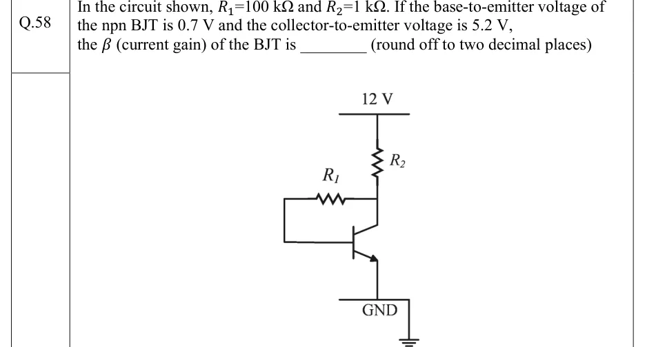
In the circuit shown, and . If the base-to-emitter voltage of the npn BJT is and the collector-to-emitter voltage is , the (current gain) of the BJT is ________ (round off to two decimal places)
 Tap to open full size
Figure description
Collector-feedback bias circuit with an npn BJT. A 12 V supply rail at the top connects through resistor R2 (1 kΩ), drawn vertically, down to the collector node. From the collector node a horizontal resistor R1 (100 kΩ) runs to the left. Its left end drops down and returns right into the base of the transistor, so R1 connects collector to base. The emitter (arrow pointing outward, npn) goes straight down to the GND line, which is tied to the earth symbol. No emitter resistor and no input source.