
IAE Academy

GATE 2018 IN Q.15: solution and answer

GATE 2018 · INQ.15 · 1 mark · NAT

Q.15 In the given circuit, assume that the opamp is ideal and the transistor has a of 20. The current (in A) flowing through the load is ______.
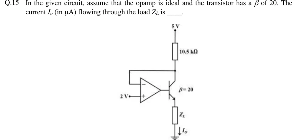
GATE 2018 IN question 15: An op-amp drives an NPN transistor.Tap to open full size
Figure from the GATE 2018 IN paper. It is part of the question.
Figure description

An op-amp drives an NPN transistor. The non-inverting (+) input of the op-amp is tied to a fixed 2 V source. The op-amp output connects to the base of the NPN transistor (labelled β = 20). The collector connects through a 10.5 kΩ resistor up to a +5 V supply. A wire from the collector node (the junction of the 10.5 kΩ resistor and the collector) runs back to the inverting (−) input of the op-amp. The emitter connects through a load Z_L (value not given) to ground. The load current I_o is marked by a downward arrow through Z_L towards ground.

Answer and solution

ANSWER

. The collector is fed back to the op-amp's inverting input, which gives positive feedback. The collector starts at 5 V, above the 2 V reference, so the op-amp output goes to its negative limit and holds the transistor in cut-off.

Official answer: 0Source: Official answer key, GATE 2018 IN (IIT Guwahati)

  1. Assumptions. The op-amp is ideal: infinite open-loop gain , zero input current, and output , limited to its supply rails. The rails are not drawn. The transistor is an NPN with and conducts only when its base–emitter junction is forward biased.

  2. Check the feedback sign before using a virtual short. holds only if the loop gives negative feedback. Follow a small rise in the op-amp output around the loop: The disturbance reinforces itself.

  3. What that means. The common-emitter stage inverts from base to collector. The collector goes back to the op-amp's inverting (−) input, which inverts a second time. Two inversions make the loop non-inverting, so the feedback is positive (regenerative). With the ideal op-amp's infinite gain the loop gain is far above 1, so the op-amp cannot stay in its linear region. The point would give and , but it is an unstable balance point. Any disturbance drives the output to a rail.

  4. Find the saturated state that is self-consistent. Suppose the transistor carries no current. The (−) input draws no current either, so no current flows in the 10.5 kΩ resistor and Then , so goes to the negative rail (or to 0 V on a single supply).

  5. Check the assumption. With no current in the emitter is at 0 V and the base is at . So and the transistor is cut off, as assumed. The circuit also starts in this state. At switch-on no collector current has flowed yet, so the collector sits at the +5 V rail, above the 2 V reference. The output swings negative, and the positive feedback keeps the transistor off.

  6. Load current. In cut-off , so

  7. Remark. 300 µA is what you get if the op-amp inputs are swapped (collector to (+), 2 V to (−)). Then a rise in lowers , the feedback is negative and the virtual short holds. So and . If the op-amp output sat at its positive limit instead, would depend on and on the op-amp's rail and current limit. None of these is given, so that state cannot produce the single number the question asks for.

KEY IDEA

Check the sign of the feedback before assuming . The CE stage inverts from base to collector, and the feedback goes to the (−) input, which inverts again. Two inversions make the feedback positive, so the op-amp saturates. The consistent state has the collector at 5 V, above the 2 V reference, with the op-amp output at its negative limit and the transistor cut off. So .

WATCH OUT FOR

Using the virtual short straight away ( V, so A and A) without checking that the feedback is negative. That answer holds only if the op-amp inputs are swapped. As drawn, the loop is regenerative and the transistor latches off.

From the GATE 2018 IN paper. Every question of this paper · Download the full paper · All 13 Biasing questions, with notes

More Biasing questions