
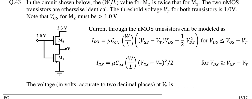
In the circuit shown below, the value for is twice that for . The two nMOS transistors are otherwise identical. The threshold voltage for both transistors is 1.0V. Note that for must be .
Current through the nMOS transistors can be modeled as
The voltage (in volts, accurate to two decimal places) at is ______.
 Tap to open full size
Figure description
Two enhancement nMOS transistors stacked in series between a 3.3 V supply and ground. Upper transistor M2: drain connected to the 3.3 V rail, source connected to the output node labelled V_x (open-circle terminal to the right), gate connected to an input node held at 2.0 V (open-circle terminal on the left labelled 2.0 V). Lower transistor M1: drain connected to node V_x, source connected to ground, gate also connected to the same 2.0 V node (a vertical wire from the 2.0 V node runs down to M1's gate, so both gates are tied to 2.0 V). Source terminals carry the nMOS arrow; no separate body terminal is drawn (body effect not considered).