
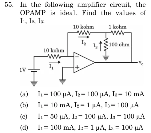
In the following amplifier circuit, the OPAMP is ideal. Find the values of I1, I2, I3:
 Tap to open full size
Figure description
Inverting op-amp. A 1 V source (positive terminal up, negative terminal grounded) feeds a 10 kohm resistor carrying current I1 (arrow to the right) into the inverting (-) input. The non-inverting (+) input is grounded. A 10 kohm feedback resistor (current I2, arrow to the right) runs from the inverting-input node, over the top, to a junction. From that junction a 100 ohm resistor goes to ground (current I3 with arrow pointing up). From the same junction a 1 kohm resistor continues to the right and connects to the op-amp output Vo.
- (A)
I1 = 100 µA, I2 = 100 µA, I3 = 10 mA
- (B)
I1 = 10 mA, I2 = 1 µA, I3 = 100 µA
- (C)
I1 = 50 µA, I2 = 100 µA, I3 = 100 µA
- (D)
I1 = 100 mA, I2 = 1 µA, I3 = 100 µA