
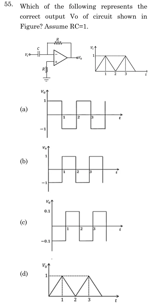
Which of the following represents the correct output Vo of circuit shown in Figure? Assume RC=1.
 Tap to open full size
Figure description
Op-amp circuit: input Vi goes through a series capacitor C to the inverting (-) terminal. A resistor R connects the output back to the inverting terminal (feedback). The non-inverting (+) terminal is grounded through a resistor R. Output is Vo. Beside it, Vi versus t is a triangular wave: rises linearly from 0 at t=0 to 1 at t=1, falls linearly to 0 at t=2, rises to 1 at t=3, then falls to 0 at t=4 (peaks at 1 marked by dashed lines). Options are Vo versus t plots. (a) Square wave: +1 for 0 to 1, -1 for 1 to 2, +1 for 2 to 3, -1 for 3 to 4. (b) Square wave: -1 for 0 to 1, +1 for 1 to 2, -1 for 2 to 3, +1 for 3 to 4. (c) Square wave of amplitude 0.1: -0.1 for 0 to 1, +0.1 for 1 to 2, -0.1 for 2 to 3, +0.1 for 3 to 4. (d) Triangular wave identical to the input, peaks of 1 at t=1 and t=3, zero at t=0, 2, 4.
- (A)
Figure — square wave between +1 and -1: +1 for 0<t<1, -1 for 1<t<2, +1 for 2<t<3, -1 for 3<t<4
- (B)
Figure — square wave between -1 and +1: -1 for 0<t<1, +1 for 1<t<2, -1 for 2<t<3, +1 for 3<t<4
- (C)
Figure — square wave between -0.1 and +0.1: -0.1 for 0<t<1, +0.1 for 1<t<2, -0.1 for 2<t<3, +0.1 for 3<t<4
- (D)
Figure — triangular wave with peaks of 1 at t=1 and t=3, same as the input