
IAE Academy

GATE 2020 IN Q.38: solution and answer

GATE 2020 · INQ.38 · 2 marks · NAT

Assuming that the opamp used in the circuit shown is ideal, the reading of the 1 Hz bandwidth, permanent magnet moving coil (PMMC) type voltmeter (in volts) is ____
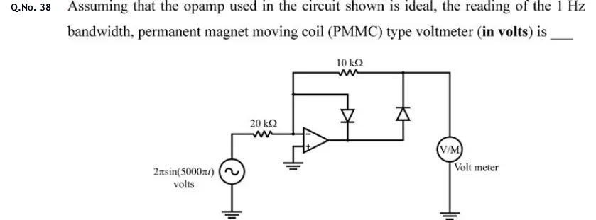
GATE 2020 IN question 38: Inverting precision half-wave rectifier.Tap to open full size
Figure from the GATE 2020 IN paper. It is part of the question.
Figure description

Inverting precision half-wave rectifier. A source 2 π sin (5000 π t) volts, with its lower terminal grounded, feeds a 20 kΩ resistor into the inverting (−) input of an op-amp. The non-inverting (+) input is grounded. The inverting-input node runs up to a top rail, and a 10 kΩ resistor on that rail connects it to the right-hand output node. Diode D1 connects the inverting-input node (anode, top) to the op-amp output (cathode, bottom). Diode D2 connects the op-amp output (anode, bottom) to the right-hand output node (cathode, top). A voltmeter (V/M, labelled 'Volt meter') is connected from the right-hand output node to ground.

Answer and solution

ANSWER

The PMMC voltmeter reads . This is the average of a half-wave rectified sine with peak .

Official answer: 1Source: Official answer key, GATE 2020 IN (IIT Delhi)

  1. Assumptions: the op-amp is ideal. Its + input is grounded, so the virtual short holds the − input at , and no current flows into either input. The PMMC meter is treated as an ideal voltmeter that draws no current. The figure does not name the diodes, so call them D1 (anode at the − node, cathode at the op-amp output) and D2 (anode at the op-amp output, cathode at the meter node ). The resistor runs from the − node to the meter node.

  2. Positive half-cycle (): a current flows into the − node, so the op-amp output swings negative. D1 conducts and closes the feedback loop. D2 has its anode at the negative op-amp output, so it is reverse biased.

  3. With D2 off, the only things connected to the meter node are the resistor and the meter. The meter draws no current, so no current flows in the resistor either, and .

  4. Negative half-cycle (): current leaves the − node through the resistor, and the op-amp output swings positive. D1 is reverse biased and D2 conducts, so the op-amp drives the meter node through D2 and feedback returns through the resistor. KCL at the virtual-ground node gives an inverting amplifier: Both diodes sit inside the feedback loop, so their forward drops do not change in either half-cycle.

  5. So is a half-wave rectified sine. It is non-zero only while , with peak . The input has , so and .

  6. A PMMC meter responds to the average (DC) value. Its bandwidth is only , and every AC component of is at or a multiple of it, so the meter shows only the DC component:

KEY IDEA

This is an inverting precision half-wave rectifier. In one half-cycle the output is held at 0 V. In the other it is , with gain . The diode drops sit inside the feedback loop, so they have no effect. A PMMC meter with a 1 Hz bandwidth reads only the DC (average) value, for a half-wave rectified sine.

WATCH OUT FOR

Common mistakes: forgetting the gain of 0.5 and using the source peak , which gives 2 V; using the full-wave average (2 V); or taking the RMS value (). A PMMC meter reads the average, and a half-wave output averages to .

From the GATE 2020 IN paper. Every question of this paper · Download the full paper · All 36 Op-amps questions, with notes

More Op-amps questions