
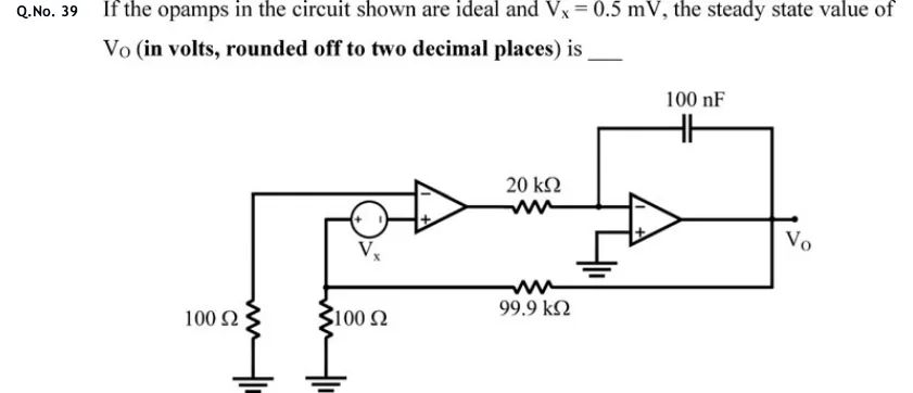
If the opamps in the circuit shown are ideal and , the steady state value of (in volts, rounded off to two decimal places) is ____
 Tap to open full size
Figure description
Two ideal op-amps in cascade. Op-amp 1 (left): its inverting (−, upper) input is connected by a wire to the top of a 100 Ω resistor whose other end is grounded (far left). Its non-inverting (+, lower) input is connected to the '−' terminal of a DC source V_X; the '+' terminal of V_X (left side) goes to a node N. Node N is the top of a second 100 Ω resistor to ground, and is also connected through a 99.9 kΩ resistor to the output V_O. Output of op-amp 1 goes through a 20 kΩ resistor to the inverting (−) input of op-amp 2 (right); op-amp 2's non-inverting (+) input is grounded; a 100 nF capacitor connects op-amp 2's inverting input to its output. The output of op-amp 2 is V_O, which feeds back to node N through the 99.9 kΩ resistor. So op-amp 2 is an inverting integrator (R = 20 kΩ, C = 100 nF) and the loop is closed from V_O through the 99.9 kΩ / 100 Ω divider and V_X back to op-amp 1's + input.