
IAE Academy

GATE 2020 IN Q.44: solution and answer

GATE 2020 · INQ.44 · 2 marks · NAT

The circuit shown uses ideal opamp powered from a supply . If the charge generated by the piezoelectric sensor is of the form , the peak detector output after 10 cycles of (in volts, rounded off to one decimal place) is ____
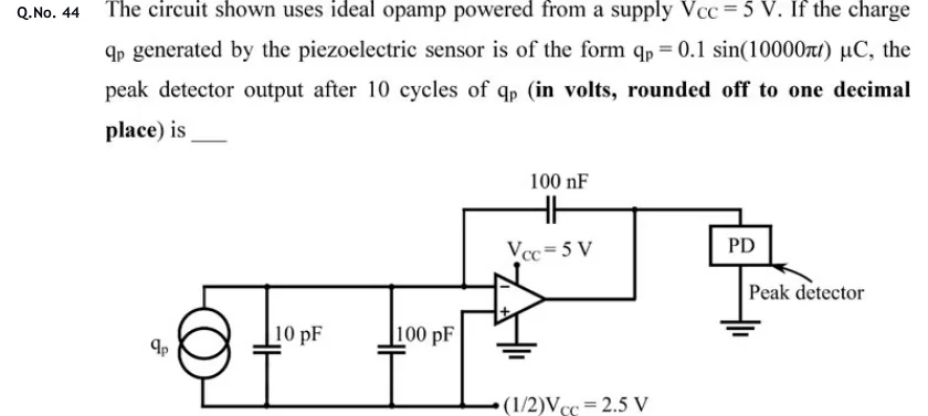
GATE 2020 IN question 44: Charge-amplifier circuit.Tap to open full size
Figure from the GATE 2020 IN paper. It is part of the question.
Figure description

Charge-amplifier circuit. On the left is the piezoelectric sensor, drawn as a current source (two overlapping circles, no arrow) labelled q_p. Two capacitors, 10 pF and 100 pF, are connected in parallel with it between a top rail and a bottom rail. The top rail goes to the inverting (-) input of the op-amp. The bottom rail (the sensor's lower terminal and the lower plates of both capacitors) runs right to a terminal labelled (1/2)V_CC = 2.5 V. The non-inverting (+) input is wired to this same bottom rail, so it sits at 2.5 V. A 100 nF capacitor connects the op-amp output back to the inverting input. The op-amp's positive supply pin is marked V_CC = 5 V and its negative supply pin goes to ground (single supply). The op-amp output feeds a block labelled PD (Peak detector), which has a ground connection below it. The PD output is the quantity asked for.

Answer and solution

ANSWER

The peak detector output is 3.5 V. The charge amplifier gives V, which swings from 1.5 V to 3.5 V without clipping, so the peak is 3.5 V.

Official answer: 3.4 to 3.6Source: Official answer key, GATE 2020 IN (IIT Delhi)

  1. Read the circuit correctly. The non-inverting input is wired to the bottom rail, so . The ground under the op-amp is its negative supply pin, so the output can swing only between and . The sensor, the and the all sit between the inverting input and this same rail. The feedback element is .

  2. Virtual short (ideal op-amp, linear operation, zero input current). Negative feedback through gives .

  3. The input capacitors carry no current. The and capacitors are connected between and the rail, so the voltage across them is always :

  4. KCL at the inverting node. Take as the sensor current entering the node. No current flows into the op-amp or the input capacitors, so all of it flows through towards the output:

  5. Integrate. Assume starts uncharged, so . Also . Then

  6. Decisive computation. The sensor's polarity is not marked. Reversing it only flips the sign of the sine term, so the output range is the same either way.

  7. Check that the op-amp stays linear. swings between and . That is well inside the to supply range, so the output never clips and the virtual-short assumption holds for the whole time.

  8. Peak detector after 10 cycles. , so and ; 10 cycles take . Since is periodic with zero average, repeats the same to swing every cycle, and nothing builds up. An ideal peak detector holds the largest value reached:

KEY IDEA

This is a charge amplifier. With the + input biased at , the virtual short puts the sensor's own capacitance and the cable capacitance () at zero volts across, so they carry no current. All of the sensor charge goes onto , and . Biasing at mid-supply lets a single-supply op-amp handle a bipolar charge signal. The peak is the bias plus .

WATCH OUT FOR

Reading the ground symbol under the op-amp as the + input's reference. That ground is the op-amp's negative supply pin; the + input is wired to the 2.5 V rail. With the + input taken as 0 V you get , which clips at the 0 V rail and gives a wrong 1.0 V. Another mistake is dividing by : the input capacitors have zero voltage across them under the virtual short, so they take no charge. The phrase '10 cycles' is a distractor. With zero-mean charge nothing accumulates, and the peak is the same in every cycle.

From the GATE 2020 IN paper. Every question of this paper · Download the full paper · All 36 Op-amps questions, with notes

More Op-amps questions