
IAE Academy

GATE 2020 IN Q.21: solution and answer

GATE 2020 · INQ.21 · 1 mark · NAT

Assume that the opamp in the circuit shown is ideal.

The value of (in ) is ____
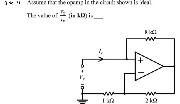
GATE 2020 IN question 21: An op-amp with its non-inverting (+) input on top and its inverting (−) input below;Tap to open full size
Figure from the GATE 2020 IN paper. It is part of the question.
Figure description

An op-amp with its non-inverting (+) input on top and its inverting (−) input below; output on the right. A test source terminal pair on the left: the upper terminal is marked +, the lower terminal is marked − and is grounded, and the voltage between them is V_x. A current I_x flows from the upper terminal (arrow pointing right) into a node connected directly to the non-inverting (+) input. From that same node, an 8 kΩ resistor goes up and across to the op-amp output (positive feedback path). The inverting (−) input is wired down to a node on the bottom line. On the bottom line, a 1 kΩ resistor connects the grounded lower terminal to that node, and a 2 kΩ resistor connects that node to the op-amp output. So the inverting input sits at the junction of a 2 kΩ (to output) and 1 kΩ (to ground) divider, and the 8 kΩ resistor links the input node (at V_x) to the output.

Answer and solution

ANSWER

. The output is , so the current through the resistor flows from the output back into the source.

Official answer: -4Source: Official answer key, GATE 2020 IN (IIT Delhi)

  1. Take the op-amp as ideal and operating in its linear region, as the question intends: no current flows into either input, and the two inputs are at the same voltage (virtual short), . enters the node wired to the non-inverting input, so .

  2. Voltage divider on the inverting side. No current enters the input, so the and resistors carry the same current and divide :

  3. Virtual short: . Seen from the input, this is a non-inverting amplifier with gain .

  4. KCL at the input node. The input draws no current, so all of flows through the resistor to the output:

  5. Input resistance: The circuit is a negative-impedance converter. In general , and here and give . Answer: .

KEY IDEA

With an ideal op-amp in linear operation, the input node sits at and the non-inverting gain fixes . The feedback resistor is the only path for . The far end of that resistor is driven to three times the input voltage, so current flows out of the source terminal instead of in, and the resistance seen at the input is negative: .

WATCH OUT FOR

Seeing an 8 kΩ resistor from the input to the output and treating it as a load to ground, which gives . Another slip is to use , the inverting gain, because the divider looks like an inverting amplifier. The source drives the input, so the gain is , the resistor current is , and the sign of the answer must be negative.

From the GATE 2020 IN paper. Every question of this paper · Download the full paper · All 36 Op-amps questions, with notes

More Op-amps questions