
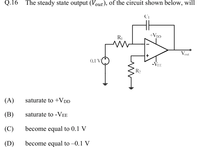
The steady state output (), of the circuit shown below, will
 Tap to open full size
Figure description
Op-amp circuit powered from +V_DD (top) and -V_EE (bottom). A 0.1 V DC source (+ terminal on top, - terminal to ground) drives resistor R1, whose other end connects to the inverting (-) input of the op-amp. Capacitor C1 is connected from the inverting input to the output (feedback path); there is no resistor across C1. The non-inverting (+) input goes to ground through resistor R2. The output node is labelled V_out. No component values are given other than the 0.1 V source.
- (A)
saturate to
- (B)
saturate to
- (C)
become equal to
- (D)
become equal to