
IAE Academy

GATE 2023 EE Q.26: solution and answer

GATE 2023 · EEQ.26 · 1 mark · MSQ

A semiconductor switch needs to block voltage V of only one polarity (V > 0) during OFF state as shown in figure (i) and carry current in both directions during ON state as shown in figure (ii). Which of the following switch combination(s) will realize the same?
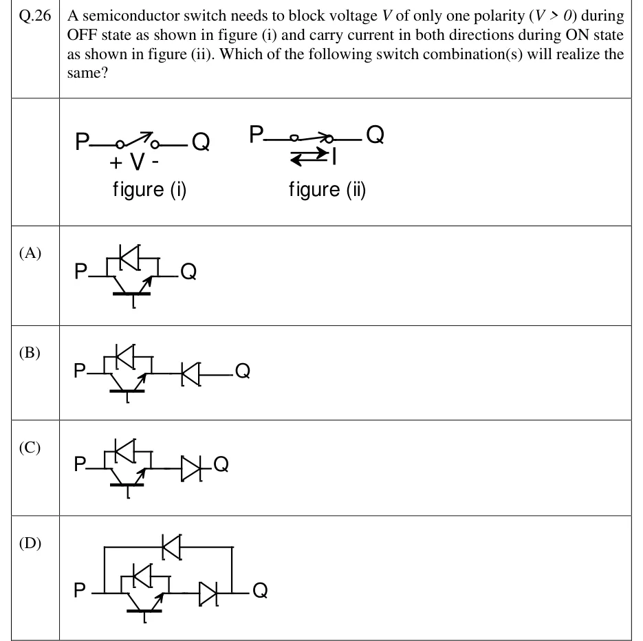
GATE 2023 EE question 26: Figure (i): a switch between terminals P (left) and Q (right), open, with voltage V marked + on the P side and - on the Q…Tap to open full size
Figure from the GATE 2023 EE paper. It is part of the question.
Figure description

Figure (i): a switch between terminals P (left) and Q (right), open, with voltage V marked + on the P side and - on the Q side. Figure (ii): the same switch closed, with a double-headed arrow showing current I may flow in both directions between P and Q. Option (A): IGBT with collector at P and emitter at Q, with an antiparallel diode across it (conducting from Q to P). Option (B): the IGBT with antiparallel diode of (A), in series toward Q with a diode that conducts from Q towards P (pointing at the IGBT). Option (C): the IGBT with antiparallel diode of (A), in series toward Q with a diode that conducts from P towards Q. Option (D): the series combination of (C) (IGBT with antiparallel diode, then a diode conducting from P towards Q) with a second diode connected across the whole combination from P to Q, conducting from Q towards P.

  1. (A)

    Figure — IGBT (collector at P, emitter at Q) with an antiparallel diode across it, between P and Q.

  2. (B)

    Figure — IGBT with antiparallel diode, in series with an extra diode that points back towards P (conducts Q to P), between P and Q.

  3. (C)

    Figure — IGBT with antiparallel diode, in series with an extra diode that points towards Q (conducts P to Q), between P and Q.

  4. (D)

    Figure — IGBT with antiparallel diode in series with a diode conducting P to Q, the whole branch connected in parallel with a diode conducting Q to P, between P and Q.

Answer and solution

ANSWER

The correct options are (A) and (D).

Official answer: A, DSource: Official answer key, GATE 2023 EE (IIT Kanpur)

  1. Required behaviour: in the OFF state the switch must block (P positive). In the ON state it must carry current both and . Blocking a negative is not required.

  2. (A) The antiparallel diode conducts . With the gate off, reverse-biases that diode and the IGBT blocks, so the OFF requirement is met. With the gate on, current flows through the IGBT and current flows through the antiparallel diode. Both directions are carried, so (A) works.

  3. (B) The series diode conducts only , so current cannot pass through the IGBT branch. Current can flow through the series diode and then the antiparallel diode. Current therefore flows in one direction only, so (B) fails.

  4. (C) The series diode conducts only . Current would have to pass through this series diode, which blocks it, whether or not the antiparallel diode is available. Current flows in one direction only, so (C) fails.

  5. (D) Current flows through the IGBT and the series diode, which conducts . Current flows through the outer diode, which conducts . With the gate off and , the outer diode is reverse-biased and the IGBT and series diode branch is blocked by the IGBT. The OFF requirement is met, so (D) works.

  6. Hence (A) and (D) realise the required switch.

KEY IDEA

The switch must block only one polarity of voltage but conduct current both ways. An IGBT with an antiparallel diode does this alone. A series diode makes the branch one-directional unless a separate diode carries the reverse current around it.

WATCH OUT FOR

Treating the antiparallel diode in (B) or (C) as a bypass for the series diode. The series diode sits in the path of the antiparallel diode as well, so the reverse path is still blocked in (C). In (B) the forward path is blocked instead.

From the GATE 2023 EE paper. Every question of this paper · Download the full paper · All 9 Switches questions, with notes

More Switches questions