
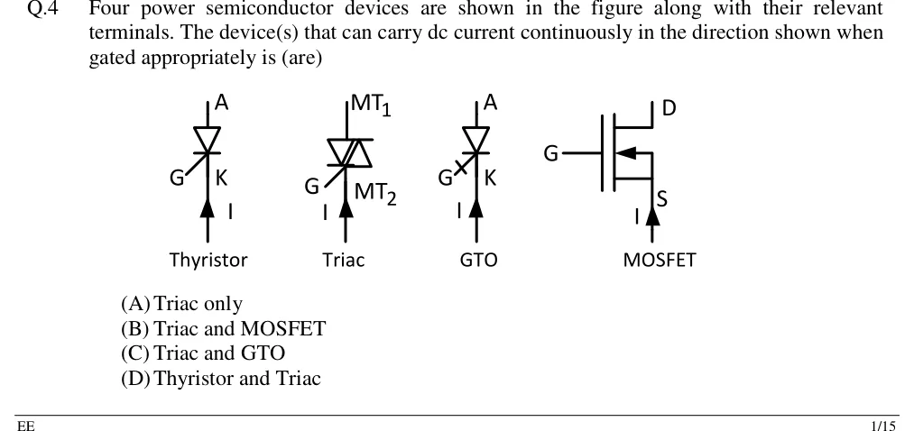
Four power semiconductor devices are shown in the figure along with their relevant terminals. The device(s) that can carry dc current continuously in the direction shown when gated appropriately is (are)
 Tap to open full size
Figure description
Four device symbols, each with an upward arrow labelled I drawn at the bottom terminal, showing the current entering the lower terminal and flowing upward through the device. (1) Thyristor: anode A at top, cathode K at bottom, gate G on the left side of the cathode end; the arrow I enters at K. (2) Triac: MT1 at top, MT2 at bottom, gate G at lower left; the arrow I enters at MT2. (3) GTO: A at top, K at bottom, gate G at lower left drawn with a cross-bar (GTO symbol); the arrow I enters at K. (4) MOSFET: gate G on the left, drain D at top, source S at bottom; the channel arrow points toward the channel from the source side, so it is an n-channel enhancement MOSFET; the arrow I enters at S, flowing from S to D.
- (A)
Triac only
- (B)
Triac and MOSFET
- (C)
Triac and GTO
- (D)
Thyristor and Triac