
IAE Academy

GATE 2023 EE Q.52: solution and answer

GATE 2023 · EEQ.52 · 2 marks · NAT

The admittance parameters of the passive resistive two-port network shown in the figure are

The power delivered to the load resistor in Watt is ________ (Round off to 2 decimal places).
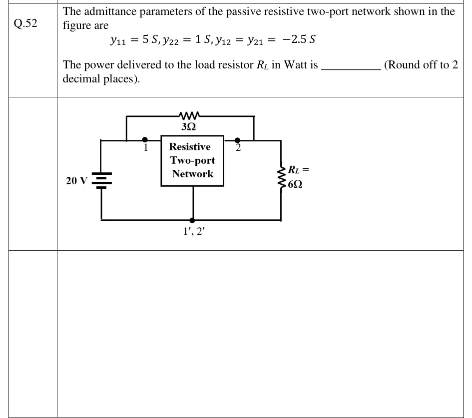
GATE 2023 EE question 52: A box labelled 'Resistive Two-port Network' has input terminal 1 (top left), output terminal 2 (top right) and a common…Tap to open full size
Figure from the GATE 2023 EE paper. It is part of the question.
Figure description

A box labelled 'Resistive Two-port Network' has input terminal 1 (top left), output terminal 2 (top right) and a common bottom terminal labelled 1', 2'. A 20 V DC source (battery symbol) is connected across port 1, between terminal 1 and the common bottom node. A load resistor R_L = 6 Ω is connected across port 2, between terminal 2 and the common bottom node. A 3 Ω resistor is connected directly between terminal 1 and terminal 2, across the top of the box, so it is in parallel with the two-port (a bridging element from the input top node to the output top node).

Answer and solution

ANSWER

The power delivered to the 6 Ω load is .

Official answer: 237 to 239Source: Official answer key, GATE 2023 EE (IIT Kanpur)

  1. The 3 Ω resistor joins the top wire at port 1 to the top wire at port 2, so electrically it sits between terminals 1 and 2. On its own it is a two-port with the same port voltages as the given network, and its port currents add to the network's. That makes it a parallel connection. The given network and the resistor share the common terminal , so this is a common-ground (three-terminal) parallel connection and adding the y-parameters is always valid. For a series element between terminals 1 and 2: and .

  2. In a parallel connection the y-matrices add:

  3. Port conditions: the source fixes . With taken as flowing into port 2, the load current flows out of port 2, so .

  4. Substitute into the output equation :

  5. Therefore .

  6. Check by nodal analysis at terminal 2. The network draws , the 3 Ω draws and the load draws . The three currents leaving the node sum to zero:

    This gives the same .

  7. Power delivered to the load:

KEY IDEA

A resistor placed across the top terminals 1 and 2 of a common-ground two-port is itself a two-port connected in parallel with it. Add its y-matrix, , to the given one. Then apply the two terminations: fixed by the source and at the load.

WATCH OUT FOR

The most common mistake is to ignore the 3 Ω bridging resistor and use the given y-parameters alone. That gives and about . Another mistake is to write the load condition as , forgetting that is defined into the port. That gives and about . Some students also give the bridging resistor instead of .

From the GATE 2023 EE paper. Every question of this paper · Download the full paper · All 11 Two-port questions, with notes

More Two-port questions