
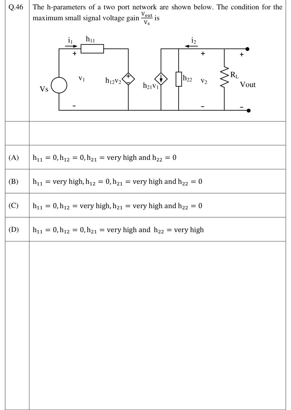
The h-parameters of a two port network are shown below. The condition for the maximum small signal voltage gain is
 Tap to open full size
Figure description
Input side (left): an independent voltage source V_s (a circle with no polarity marks) in the left vertical branch. From its top terminal a wire runs right through a resistor box labelled h_11. Current i_1 is marked by a right-pointing arrow above this wire, between the source and h_11. Voltage v_1 is marked + on the top wire just left of h_11 and − on the bottom rail, so it is across the source terminals. Right of h_11 the wire turns down through a dependent voltage source (diamond) labelled h_12v_2, + at top and − at bottom, to the bottom rail. Output side (right, on a separate top wire that starts above the first output element): three elements in parallel between this top wire and the bottom rail. From left to right they are a dependent current source (diamond) labelled h_21v_1 (printed with v_1, not i_1) with its arrow pointing DOWN, an admittance box labelled h_22, and a load resistor R_L. Between the h_22 box and R_L, current i_2 is marked by a LEFT-pointing arrow on the top wire (from the load into the network), and voltage v_2 is marked + at top and − at bottom. At the far right, two filled terminal dots (top and bottom) carry V_out, + at top and − at bottom, so V_out = v_2, the voltage across R_L. The bottom rail is one continuous wire from V_s to the bottom output terminal.
- (A)
- (B)
- (C)
- (D)