
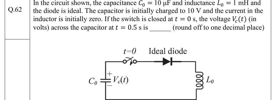
In the circuit shown, the capacitance and inductance and the diode is ideal. The capacitor is initially charged to 10 V and the current in the inductor is initially zero. If the switch is closed at s, the voltage (in volts) across the capacitor at s is ______ (round off to one decimal place)
 Tap to open full size
Figure description
A single series loop. The left branch is capacitor C0, drawn vertically, with its + terminal at the top and - terminal at the bottom, labelled V_c(t). From the top of C0 a wire runs right through a switch (labelled t=0, open before t = 0 and closing at t = 0), then through an ideal diode whose anode is on the left and cathode on the right (arrow pointing right, away from the capacitor's + terminal). The wire continues to the top right corner and down through inductor L0 on the right branch, then along the bottom wire back to the - terminal of C0. There are no other elements.