
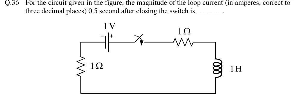
For the circuit given in the figure, the magnitude of the loop current (in amperes, correct to three decimal places) 0.5 second after closing the switch is ________.
 Tap to open full size
Figure description
A single series loop drawn as a rectangle. Top side, left to right: a 1 V battery (negative terminal marked '-' on the left, positive terminal '+' on the right), then a switch drawn in the open position (no closing-time label is printed), then a 1 Ω resistor. Right side: a 1 H inductor running from the top-right corner to the bottom-right corner. Bottom side: a plain wire. Left side: a 1 Ω resistor running from the bottom-left corner up to the top-left corner, where it meets the battery's negative terminal. Everything is in one series loop: battery, switch, 1 Ω, 1 H, then 1 Ω back to the battery.