
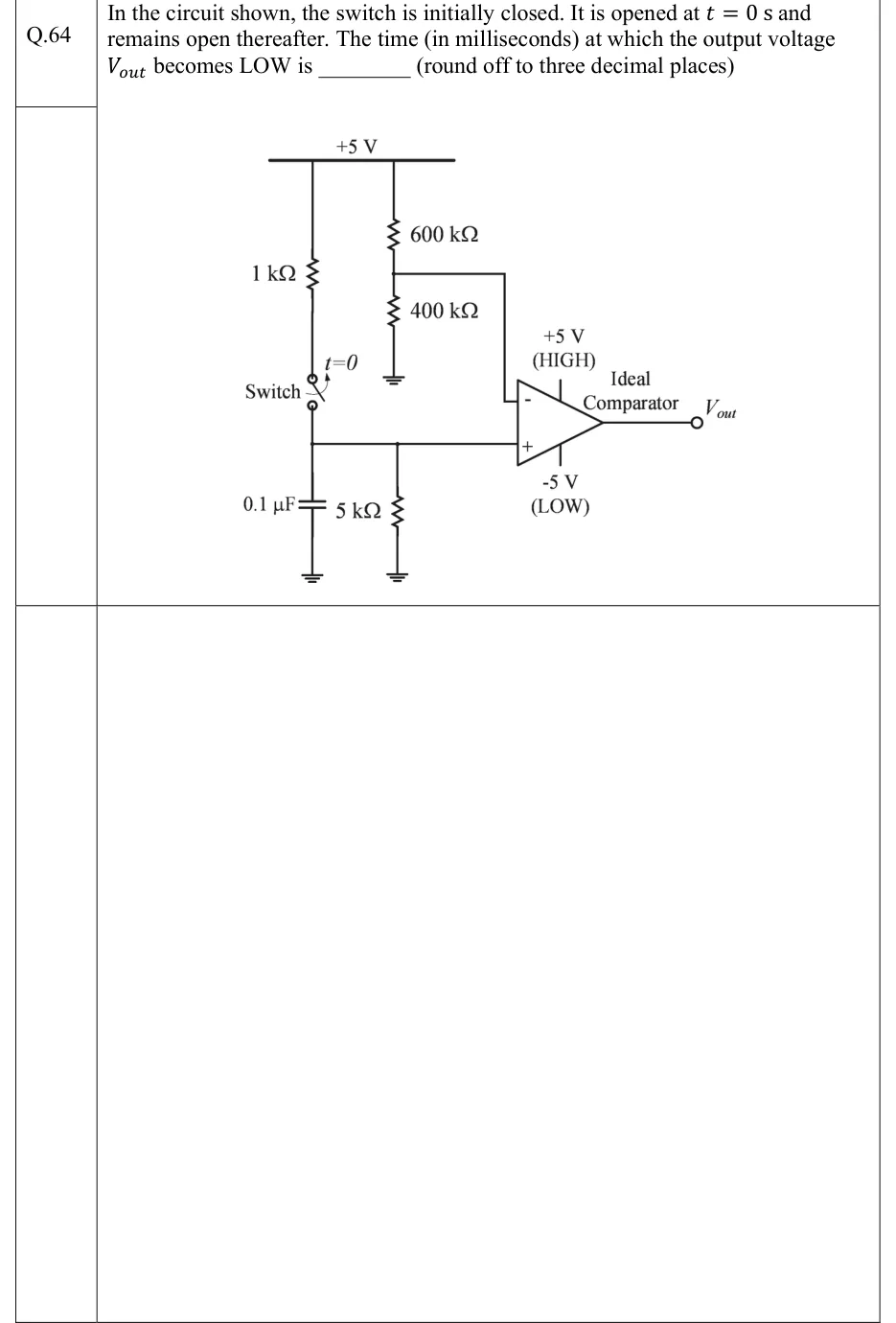
In the circuit shown, the switch is initially closed. It is opened at s and remains open thereafter. The time (in milliseconds) at which the output voltage becomes LOW is ________ (round off to three decimal places)
 Tap to open full size
Figure description
A +5 V supply rail runs along the top. Left branch: a 1 kΩ resistor hangs from the +5 V rail down to a switch labelled 'Switch'. The switch is shown closed and is marked t=0 with an arrow showing that it opens at t = 0. The lower terminal of the switch goes to node X. At node X, a 0.1 µF capacitor goes to ground, a 5 kΩ resistor goes to ground, and a wire goes to the non-inverting (+) input of an ideal comparator. Right branch: a potential divider hangs from the +5 V rail, with 600 kΩ on top and 400 kΩ below it to ground. The junction of the 600 kΩ and 400 kΩ resistors goes to the inverting (−) input of the comparator. The comparator is labelled 'Ideal Comparator'. Its output saturates at +5 V (HIGH) and −5 V (LOW), and the output terminal is labelled V_out.