
IAE Academy

GATE 2023 EE Q.29: solution and answer

GATE 2023 · EEQ.29 · 1 mark · NAT

The value of parameters of the circuit shown in the figure are
, , , ,
For time , the circuit is at steady state with the switch 'K' in closed condition. If the switch is opened at , the value of the voltage across the inductor () at in Volts is ________ (Round off to 1 decimal place).
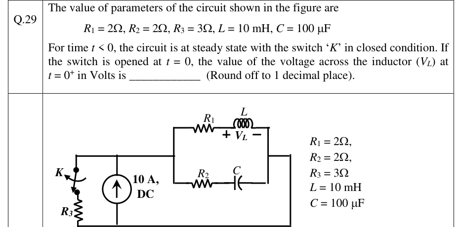
GATE 2023 EE question 29: A 10 A DC current source (arrow pointing up) is connected between a bottom wire (node B) and a top wire (node A).Tap to open full size
Figure from the GATE 2023 EE paper. It is part of the question.
Figure description

A 10 A DC current source (arrow pointing up) is connected between a bottom wire (node B) and a top wire (node A). On the left, between A and B, is a series branch of switch K (closed for t < 0, opens at t = 0) and resistor R3 = 3 Ω, with K at the top next to node A and R3 below it. On the right, node A continues to a vertical wire that feeds two parallel branches running left to right: the upper branch is R1 = 2 Ω in series with inductor L = 10 mH, with V_L marked across the inductor, + on the left (R1 side) and − on the right; the lower branch is R2 = 2 Ω in series with capacitor C = 100 μF. The right ends of the two branches join at a vertical wire, and a wire runs from there down and back along the bottom to node B. So three branches are in parallel across the current source: (K + R3), (R1 + L) and (R2 + C). The parameter values are repeated beside the figure.

Answer and solution

ANSWER

Official answer: 7.9 to 8.1Source: Official answer key, GATE 2023 EE (IIT Kanpur)

  1. Topology: the source's top node and bottom node carry three parallel branches, , and . The right ends of the and branches are wired straight back to .

  2. Steady state for (DC): acts as a short and as an open, so the splits between and only. By current division, , flowing from through and .

  3. No current flows in , so the capacitor holds the full node voltage: . Check: carries , and .

  4. Continuity at switching: and .

  5. At , is open, so the branch carries nothing. KCL at node : through and .

  6. KVL on the – branch gives the node voltage: . The node voltage jumps from to . Only and have to be continuous.

  7. KVL on the – branch: , positive at the marked terminal (the side).

  8. Sanity check: . So is rising, as it must: in the new steady state is open and the whole flows through and .

KEY IDEA

At , treat the inductor as a current source and the capacitor as a voltage source, both values taken from the DC steady state. Once opens, the source current has only two paths. The inductor fixes its branch at , so the – branch must take . That sets the node voltage at , and is whatever leaves over: .

WATCH OUT FOR

Treating the node voltage as continuous (keeping at ) gives . Only and are continuous; jumps to because the capacitor branch now takes through . Other slips: forgetting the drop, sending current through the – branch in the DC analysis (the capacitor is open), or letting jump straight to .

From the GATE 2023 EE paper. Every question of this paper · Download the full paper · All 20 Transients questions, with notes

More Transients questions