
IAE Academy

GATE 2023 EC Q.44: solution and answer

GATE 2023 · ECQ.44 · 2 marks · MCQ

The switch was closed and was open for a long time. At , switch is opened and is closed, simultaneously. The value of , in amperes, is
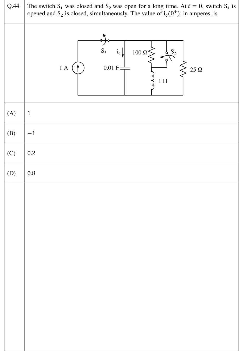
GATE 2023 EC question 44: Parallel circuit with a common bottom rail and a top rail.Tap to open full size
Figure from the GATE 2023 EC paper. It is part of the question.
Figure description

Parallel circuit with a common bottom rail and a top rail. From left to right: (1) A 1 A independent current source (arrow pointing up) in the leftmost branch. Its top terminal connects to the top rail through switch S_1, which sits on the top wire just right of the source branch, so S_1 is in series with the source. S_1 is drawn with an arrow showing it opening. (2) A 0.01 F capacitor from the top rail to the bottom rail. The current i_c is marked flowing downward into the capacitor branch. (3) A branch with a 100 Ω resistor from the top rail down to a middle node M, then a 1 H inductor from M to the bottom rail. (4) Switch S_2: its upper terminal is wired to the top rail and its lower terminal is wired left to node M, the junction between the 100 Ω resistor and the inductor. Closing S_2 therefore short-circuits the 100 Ω resistor. S_2 is drawn with an arrow showing it closing. (5) A 25 Ω resistor from the top rail to the bottom rail in the rightmost branch. Before t = 0: S_1 closed, S_2 open. At t = 0: S_1 opens and S_2 closes at the same instant.

  1. (A)

    1

  2. (B)

  3. (C)

    0.2

  4. (D)

    0.8

Answer and solution

ANSWER

, option (B). The capacitor, still at , supplies to the resistor and to the inductor, so its current flows opposite to the marked arrow.

Official answer: BSource: Official answer key, GATE 2023 EC (IIT Kanpur)

  1. Steady state for ( closed, open): the capacitor acts as an open circuit and the inductor as a short circuit. The 1 A source then feeds two parallel paths: the resistor (in series with the shorted inductor) and the resistor.

  2. Top-rail voltage, which is also the capacitor voltage:

  3. Inductor current, flowing downward through the branch: . Check: the resistor carries , and , which is the source current.

  4. Continuity rules: and . At the capacitor therefore behaves as a source and the inductor as a current source.

  5. Circuit at : is in series with the current source, so opening it disconnects the source from the network. Closing shorts the resistor, so that resistor carries no current and the inductor is connected directly between the rails. The capacitor, the inductor and the resistor are now in parallel, all at . The inductor voltage jumps from to , which is allowed: only the inductor current has to be continuous.

  6. Current in the resistor: , flowing downward.

  7. KCL at the top node, taking every branch current downward (the direction of the marked ). No source current enters, because is open:

  8. The minus sign means the capacitor is discharging, so current flows upward through it, against the marked arrow. This is option (B). The values and are not needed to find the value.

KEY IDEA

Work out and from the DC steady state, with the capacitor open and the inductor shorted. At , replace the capacitor with a voltage source of and the inductor with a current source of , redraw the circuit for the new switch positions, and apply KCL. The sign of is set by the marked arrow direction.

WATCH OUT FOR

Answering by dropping the sign: the capacitor current actually flows upward, against the marked . Other traps: choosing because you forgot the inductor keeps drawing its after the switch; choosing because you ignored the resistor; still treating the capacitor as open at and getting ; and thinking the open leaves the source in the circuit.

From the GATE 2023 EC paper. Every question of this paper · Download the full paper · All 20 Transients questions, with notes

More Transients questions