
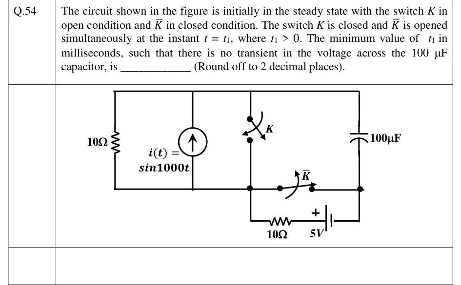
The circuit shown in the figure is initially in the steady state with the switch in open condition and in closed condition. The switch is closed and is opened simultaneously at the instant , where . The minimum value of in milliseconds, such that there is no transient in the voltage across the capacitor, is ________ (Round off to 2 decimal places).
 Tap to open full size
Figure description
Three nodes: a top rail T, a bottom-left node M (drawn as a dot below switch K), and a bottom-right node R (a dot below the capacitor). Between T and M, from left to right, are three parallel branches: a 10 Ω resistor; an independent current source i(t) = sin 1000t with its arrow pointing up, so it drives current from M into T; and switch K, drawn open, connecting T to M. The 100 capacitor connects T to R on the right. Switch K, drawn closed, connects M to R directly along the bottom wire. Below that wire a second branch also runs from M to R: from M down, then a 10 Ω resistor, then a 5 V battery. The battery's positive terminal (long plate, marked +) faces the resistor and hence M, and its negative terminal faces R. Before t_1: K open, K closed. At t = t_1: K closes and K opens.