
IAE Academy

GATE 2018 EE Q.8: solution and answer

GATE 2018 · EEQ.8 · 1 mark · MCQ

In the figure, the voltages are , and . The circuit is in sinusoidal steady state, and . , and are the average power outputs. Which one of the following statements is true?
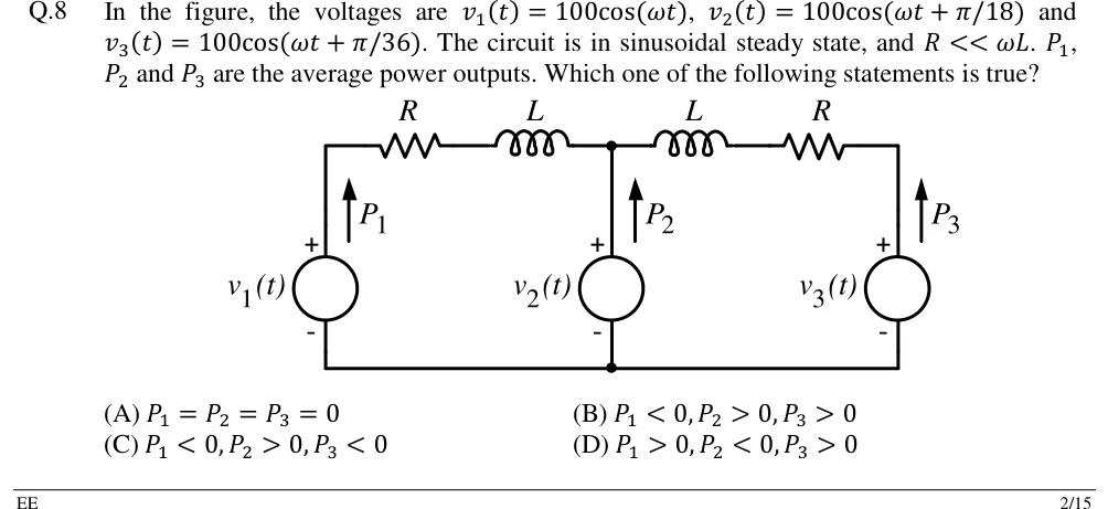
GATE 2018 EE question 8: Three ideal voltage sources share a common bottom (ground) wire.Tap to open full size
Figure from the GATE 2018 EE paper. It is part of the question.
Figure description

Three ideal voltage sources share a common bottom (ground) wire. Left: source v_1(t), + terminal at top, with an upward arrow labelled P_1 beside it (power output). Middle: source v_2(t), + at top, upward arrow P_2. Right: source v_3(t), + at top, upward arrow P_3. Top rail: from the top of v_1 a series resistor R then an inductor L lead to the middle node, which is the top of v_2. From the middle node an inductor L then a resistor R lead to the top of v_3. So each outer source is connected to the middle source through an identical series branch R + j ω L; the bottom terminals of all three sources are joined.

  1. (A)

  2. (B)

  3. (C)

  4. (D)

Answer and solution

ANSWER

Option (C): , , . The middle source leads both of the others, so it supplies real power to and to .

Official answer: CSource: Official answer key, GATE 2018 EE (IIT Guwahati)

  1. Phasors (rms): and , so , , . Write , so . All three magnitudes are equal; only the phase angles differ.

  2. The bottom terminals of all three sources are joined, so each outer source is connected straight to the top of through one series branch , where . The order of and inside a branch makes no difference. Because , each branch is almost a pure reactance.

  3. Power output of : the current leaving its terminal is , so . Put , where is the angle by which leads , and :

  4. Sign of : exactly when , that is when . Since , this certainly holds. Dropping (so ) gives . So absorbs power.

  5. Power output of : it is connected only to , through the same . With leaving its terminal, and leading by , the same algebra gives . This is negative because . Approximately, . So also absorbs power.

  6. Power output of : the current leaving its terminal is . Each branch now contributes instead of : since every term is positive. Approximately, . Check: . That is exactly the loss in the two resistors, so energy balances.

  7. So , and , which is option (C). This matches the rule of thumb for a nearly lossless inductive link: real power flows from the leading voltage to the lagging one. leads both of its neighbours, so it supplies both.

KEY IDEA

When sources of equal magnitude are joined by a mostly inductive branch (), real power flows from the source whose voltage leads to the one that lags, . Compare each source only with the source it is actually wired to. Here and are each wired to , and leads both of them.

WATCH OUT FOR

Picking (A) because all three magnitudes are equal, when it is the phase difference that drives real power through a reactance. Another mistake is picking (B): comparing with (it leads by ) and calling it a supplier. But is connected only to , which leads it by , so absorbs power.

From the GATE 2018 EE paper. Every question of this paper · Download the full paper · All 34 AC, power & resonance questions, with notes

More AC, power & resonance questions