
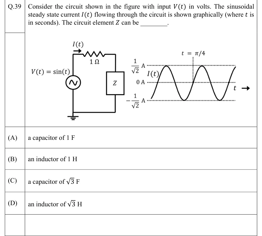
Consider the circuit shown in the figure with input in volts. The sinusoidal steady state current flowing through the circuit is shown graphically (where is in seconds). The circuit element can be ________.
 Tap to open full size
Figure description
Left: a single series loop. An AC voltage source labelled V(t) = sin (t) sits on the left branch, and the bottom-left node is connected to ground. From the top of the source a wire runs right through a 1 Ω resistor, then down through a box labelled Z on the right branch, then back along the bottom wire to the source. An arrow above the top wire, at its left end just before the resistor, points right and is labelled I(t), so the current flows clockwise (source top → resistor → Z → bottom). Right: a plot of I(t) against t, with an arrow labelled t pointing right. The origin t = 0 is not marked. Horizontal dotted reference lines are drawn at 1 √ 2 A, 0 A and - 1 √ 2 A. The current is a sinusoid that just touches ± 1 √ 2 A. It is drawn from just above a trough at the left edge to just before a peak at the right edge, a little over two cycles. A vertical dotted line labelled t = π /4 meets the 0 A line exactly where the current crosses zero going UPWARD: the rising zero crossing that follows the first full trough and comes before the second peak.
- (A)
a capacitor of 1 F
- (B)
an inductor of 1 H
- (C)
a capacitor of F
- (D)
an inductor of H