
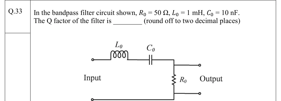
In the bandpass filter circuit shown, , , . The Q factor of the filter is ________ (round off to two decimal places)
 Tap to open full size
Figure description
Two-port circuit, input terminals on the left, output terminals on the right. From the upper input terminal, an inductor L_0 and a capacitor C_0 are connected in series along the top wire, in that order from left to right. After C_0 the top wire meets a vertical resistor R_0, which runs down to the bottom wire. The bottom wire is common from the lower input terminal to the lower output terminal. The output terminals are taken directly across R_0 (upper output from the top of R_0, lower output from its bottom). Labels: 'Input' on the left, 'Output' on the right. So it is a series R-L-C loop with the output voltage across the resistor.