IAE Academy

GATE EE · IN

Measuring voltage, current, power, energy and power factor

A meter does not simply show "the voltage". A PMMC movement responds to the average value. Moving-iron, electrodynamometer, electrostatic, thermal and true-rms meters respond to the rms value. Rectifier and peak-reading meters respond to an average or a peak but are scaled to show the rms value of a sine wave, so on other waveforms they are generally in error. Questions on this topic ask what a given meter reads on a given waveform, how shunts, multipliers, probes and instrument transformers scale a quantity, and what loading does to the reading. They also ask how wattmeters, the two-wattmeter method, energy meters and power-factor meters turn readings into power, energy and power factor, each with its own error terms and conditions.

8 previous-year questions · 8 solved · 6 practice questions

How analog meters deflect, and what each one reads

Every analog indicating instrument needs three torques. The deflecting torque is produced by the quantity being measured. The controlling torque, usually from a spiral spring (), opposes it so that each value gives a definite deflection. The damping torque acts only while the pointer is moving, and brings it to rest quickly with little or no overshoot.

Which value a meter reads depends on how its deflecting torque varies with the current. The moving system cannot follow torque pulsations at 50 Hz, so it settles at the average torque. If torque is proportional to (PMMC), the meter reads the average of . If torque is proportional to (moving iron, electrodynamometer, thermal), it responds to the mean of and its scale is marked in the square root of that mean, which is the rms value.

STEADY DEFLECTION (SPRING CONTROL)

is the spring constant in N·m/rad. The pointer settles where the deflecting torque equals the controlling torque. With gravity control, instead, where is the control weight times its distance from the spindle.

PMMC DEFLECTION

is the number of turns, the gap flux density, the coil area and . With a varying current the inertia of the moving system averages the torque, so follows the average (DC) value. The scale is linear, and the pointer tries to deflect backwards if the current reverses.

MOVING-IRON DEFLECTION

Derived from stored energy. Torque is proportional to , so the direction of deflection does not depend on polarity and is the rms value on AC. The scale is square-law unless the vane is shaped so that falls as increases.

ELECTRODYNAMOMETER DEFLECTING TORQUE (AVERAGE)

and are the rms currents in the fixed and moving coils, and is the angle between them (on DC, use the DC currents with ). Used as an ammeter or voltmeter, it reads rms and has the same calibration on DC and AC.

ELECTROSTATIC VOLTMETER TORQUE

Works only as a voltmeter, and responds to rms. Its torque is very small at low voltages, so it is used mainly for high voltages. On DC it draws no steady current once the plates have charged.

Instrument

Responds to

Scale

Use

Watch for

PMMC

Average (DC) value

Linear

DC only

Reads zero on a zero-mean AC wave; very low power drawn; eddy-current damping in the metal former

Moving iron

RMS

Square-law (cramped at the low end unless the vane is shaped)

AC and DC

Hysteresis error (DC); frequency and eddy-current errors (AC); stray fields; air-friction damping

Electrodynamometer

RMS as ammeter/voltmeter; mean of as wattmeter

Square-law as ammeter/voltmeter; nearly uniform as wattmeter

AC and DC; transfer instrument

Weak working field (no iron), so stray fields matter; draws more power than a PMMC

Rectifier type (PMMC + diodes)

Average of the rectified wave, scale marked in rms of a sine

Nearly linear

AC

Form-factor error on non-sinusoidal waves; diode drop at low voltages; temperature

Thermocouple (thermal)

True rms

Square-law

AC and DC, up to high frequencies

Heater burns out on small overloads; slow response

Electrostatic

RMS (voltage only)

Square-law

High-voltage AC and DC

Very small torque

Peak-reading (electronic)

Peak, scale marked in rms of a sine

Linear

AC

Error on any wave whose crest factor is not

True-rms (electronic)

RMS of the actual waveform

Linear (digital)

AC, or AC + DC when DC-coupled

Crest-factor and bandwidth limits

Induction

Interaction of two alternating fluxes

—

AC only (energy meters)

Frequency- and waveform-dependent

WORKED EXAMPLE

A moving-iron ammeter has a control-spring constant N·m/rad, and its inductance varies with deflection as H, with in radians. Find the deflection for a current of 5 A (rms), and the current that gives a deflection of 1 rad.

Solution
  1. H/rad.

  2. Equilibrium . With torques in N·m: .

  3. rad .

  4. For rad: H/rad, so , giving and A.

Answer: 1.25 rad (71.6°) at 5 A; 4.08 A for 1 rad. Solving the equilibrium in general gives rad with in amperes, so the deflection is not proportional to the current: the scale is non-linear.

EXAM TIP

A PMMC meter on a pure sinusoid reads zero. On DC plus AC it reads only the DC component. The electrodynamometer instrument has no iron, so it has no hysteresis error and reads the same rms value on DC and AC. That is why it serves as the transfer instrument: calibrate it on DC, then use it on AC.

Waveform values: rms, average, form factor and meter errors

What a meter shows depends on the waveform as well as on the meter. For any periodic wave, keep three numbers: its average, its rms value and its peak. For form-factor work, the average means the mean of over a full period, which equals the half-cycle average of a symmetric wave. The ratios of these values are the form factor and the crest factor.

Rectifier and peak-reading meters respond to an average or a peak, but their scales are marked in rms using the ratios of a sine. So they read correctly on a sinusoid, and on another wave only if its form factor (for an average-responding meter) or crest factor (for a peak-responding meter) happens to equal a sine's. For any other wave, work out what the movement actually responds to, then multiply by the sine scale factor.

RMS AND AVERAGE VALUES

is one full period. A PMMC reads the signed mean , which is zero for a symmetric AC wave. Do not confuse it with .

FORM FACTOR AND CREST (PEAK) FACTOR

For a sine wave, and .

Waveform (peak )

(mean of )

Sine

1.111

1.414

Square, , 50% duty

1

1

Triangle or sawtooth, zero mean

1.155

1.732

Half-wave rectified sine

1.571

2

Full-wave rectified sine

1.111

1.414

RMS OF A WAVE WITH DC AND HARMONICS

is the DC component, and are the rms values of components at different frequencies, whose cross-products average to zero. For two sinusoids of the same frequency, add them as phasors first.

FULL-WAVE RECTIFIER METER READING

Applies to an average-responding full-wave meter whose scale is marked in rms of a sine. is the mean of . The reading is correct only when the wave's .

HALF-WAVE RECTIFIER METER READING

Applies to an average-responding half-wave meter with its scale marked in rms of a sine. Only the conducting half-cycle contributes. Reversing the leads measures the other half, which gives a different reading on an asymmetric wave.

PEAK-READING METER

Applies to a peak-responding meter with its scale marked in rms of a sine. It is in error on any wave whose crest factor is not .

FORM-FACTOR ERROR OF AN AVERAGE-RESPONDING METER

Applies to a full-wave average-responding meter calibrated for a sine, with computed from the mean of . The error is a percentage of the TRUE rms of the applied wave. Square wave (): . Triangle (): .

What each meter shows for $v = V_0 + v_{ac}(t)$

  1. PMMC: the signed mean, .

  2. Moving iron, electrodynamometer, thermal, and DC-coupled true-rms: .

  3. AC-coupled true-rms (blocking capacitor at the input): only.

  4. Full-wave rectifier meter (no blocking capacitor): the mean of . Work out first. If the wave never goes negative, this is simply .

WORKED EXAMPLE

A symmetric triangular voltage with a peak of 12 V and zero mean is measured with a full-wave rectifier-type voltmeter whose scale is calibrated to read the rms value of a sinusoid. Find the reading, the true rms value, and the percentage error relative to the true rms.

Solution
  1. Mean of for a triangle: V.

  2. Reading V.

  3. True rms V.

  4. Error . Check with the form factors: .

Answer: The meter reads 6.66 V against a true rms of 6.93 V, an error of about −3.8% (it reads low).

EXAM TIP

A sine-calibrated rectifier meter on pure DC of volts reads if it is full-wave, and if it is half-wave and the polarity lets the diode conduct. The movement sees the average, and the scale multiplies by the sine factor whatever the input is.

Extending ranges: shunts, multipliers and loading

A PMMC movement is a small current meter: its full-scale current is somewhere between tens of microamperes and a few milliamperes, and its coil resistance is . To measure a larger current, a low-resistance shunt in parallel carries the excess. To measure voltage, a high-resistance multiplier in series limits the current to at the range voltage.

Every meter disturbs the circuit it measures. A voltmeter draws current, which lowers the voltage it is connected across. An ammeter adds its own resistance to the loop. Replace the circuit the meter sees with its Thevenin equivalent and the error follows directly.

AMMETER SHUNT

is the multiplying power: the new full-scale current divided by the movement's full-scale current. The shunt and the movement share the same voltage.

VOLTMETER MULTIPLIER

is the desired full-scale voltage. The total meter resistance is .

VOLTMETER SENSITIVITY AND RESISTANCE

The voltmeter's resistance depends on the RANGE selected, not on the reading. A higher sensitivity (smaller ) means less loading.

AC SENSITIVITY OF A RECTIFIER VOLTMETER

For a PMMC movement with ideal diodes and a scale marked in rms of a sine, where . A sine of rms value has a mean of after full-wave rectification and after half-wave rectification, so the total resistance for full scale on an AC range is or .

VOLTMETER LOADING

and form the Thevenin equivalent seen from the voltmeter's terminals, and is the true (unloaded) voltage. The error is a percentage of the true value and is always negative.

AMMETER INSERTION ERROR

is the Thevenin resistance of the loop the ammeter is inserted into, and is the ammeter's resistance. The error is a percentage of the true current, and the current is always reduced.

FREQUENCY-INDEPENDENT SHUNT FOR AN AC (MOVING-IRON) AMMETER

When the meter and shunt branches have equal time constants, the current divides in the same ratio at every frequency.

FREQUENCY COMPENSATION OF A MOVING-IRON VOLTMETER

Here is the coil inductance and is the series (swamping) resistance, with the capacitor connected across . The value (more exactly ) keeps the impedance nearly constant over the working frequency range, so the voltmeter reads nearly the same on DC and on AC. It assumes the coil's own resistance is small compared with .

Practical details

  1. Swamping resistance: a manganin resistor (near-zero temperature coefficient), several times the coil resistance, is placed in series with the copper coil. It makes the total resistance, and hence the calibration, nearly independent of temperature.

  2. Ayrton (universal) shunt: a single tapped shunt serves a multirange ammeter, and the movement is never left without a shunt while ranges are switched.

  3. Multirange voltmeter: a series multiplier is switched in for each range, and the meter's resistance on each range is range.

WORKED EXAMPLE

A PMMC movement with a full-scale current of 1 mA and a resistance of 100 Ω is converted to a 0–100 V voltmeter. Find the multiplier and the sensitivity. The voltmeter is then connected across the lower resistor of a divider made of two 50 kΩ resistors across a 100 V DC source. Find its reading and the loading error.

Solution
  1. Multiplier: kΩ.

  2. Sensitivity: /V, so kΩ.

  3. Seen from the lower resistor: V (the true voltage) and kΩ.

  4. Reading: V.

  5. Error: , which agrees with .

Answer: 99.9 kΩ; 1 kΩ/V; the meter reads 40 V instead of 50 V, a loading error of −20% of the true value.

EXAM TIP

Switching the same meter to a higher range raises in proportion ( range), so the loading error falls. But the reading then sits lower on a coarser scale, so when the meter's accuracy is specified as a percentage of full scale, the possible error as a fraction of the reading grows. When a question gives two ranges, work out for each.

Probes, scaling and true-rms meters

Before a current or voltage reaches a meter, it is scaled to the meter's range and picked up either with or without electrical contact. Voltage is scaled down by resistive (or compensated RC) dividers and by potential transformers. Current is scaled by shunts, current transformers, Hall-effect sensors and Rogowski coils.

Probe / sensor

Contact?

AC / DC

Principle

Notes

Current shunt + voltmeter

Contact (inserted in series)

AC and DC

The circuit must be broken to insert it; heating and a voltage drop (burden)

Clamp-on CT

Non-contact

AC only

Transformer action; the conductor is a one-turn primary

Cannot sense DC; clamp only one conductor

Hall-effect clamp

Non-contact

AC and DC

Hall voltage proportional to the flux in the core gap, which is proportional to

Zero the offset before a DC measurement

Rogowski coil

Non-contact

AC only

Air-cored coil, , followed by an integrator

No core to saturate; flexible; suits large or fast currents

Passive 10:1 voltage probe

Contact

AC and DC

Compensated RC divider with the scope input

Needs compensating; with a 1 MΩ scope input, the circuit under test sees 10 MΩ

High-voltage probe

Contact

AC and DC

Resistive (compensated) divider, e.g. 1000:1

Scales kV down to the meter's range

Differential probe

Contact

AC and DC

Measures without grounding either point

For floating measurements, such as across a switch in a converter

Non-contact voltage detector

Non-contact

AC only

Capacitive coupling to the live conductor

Shows that voltage is present, not its value; cannot detect DC

COMPENSATED VOLTAGE PROBE (RC DIVIDER)

includes the capacitance of the scope input and the cable. Example: a 9 MΩ tip resistor with a 1 MΩ ∥ 18 pF input gives 10:1 and needs pF. The circuit under test then sees 10 MΩ in parallel with 1.8 pF. When the condition holds, the division ratio is the same at all frequencies.

Adjust a probe's compensation with a square test wave. When the tops are flat. If is too small (under-compensated), high frequencies are attenuated more than DC and the leading edges are rounded. If is too large (over-compensated), the edges overshoot.

SCALING THROUGH INSTRUMENT TRANSFORMERS

is the nominal ratio, primary:secondary. For example, a 100/5 A CT has , and an 11 kV/110 V PT has . Ratio and phase-angle errors are neglected here.

A meter that responds to rms must, in effect, square the signal, average it and take the square root. A thermal meter does this physically: the heater power is proportional to , and the thermocouple EMF is proportional to the temperature rise. An electronic true-rms meter does it with an analog rms converter or by sampling and computing. Its limits are specified as a maximum crest factor (a narrow pulse with a high peak-to-rms ratio can saturate the converter) and a bandwidth. A true-rms meter that is AC-coupled on its AC range reads only the AC part of a wave that contains DC; a DC-coupled one reads .

SAMPLED RMS

Take the samples over a whole number of periods, at more than twice the highest significant harmonic frequency.

EXAM TIP

Never open the secondary of a CT while its primary is carrying current. The primary current is set by the line, not by the CT. Without the opposing mmf of the secondary, the core flux rises sharply, which induces a dangerously high secondary voltage and can leave the core magnetised. Short the secondary before removing a meter. A PT's secondary, by contrast, must never be short-circuited.

EXAM TIP

A clamp meter measures the NET current passing through its jaws. Clamp a single conductor. Around a cable that carries both the go and return conductors of the same circuit, the reading is close to zero.

Power in DC and single-phase AC: the wattmeter and its errors

In a DC circuit, power is , but an ammeter and a voltmeter cannot both be connected ideally. Either the ammeter also carries the voltmeter's current, or the voltmeter also sees the ammeter's voltage drop. The product then includes one meter's own loss.

DC POWER, VOLTMETER ACROSS THE LOAD

The ammeter carries the load current plus the voltmeter's current. This connection is preferred for low-voltage, high-current loads.

DC POWER, AMMETER NEXT TO THE LOAD

The voltmeter reads the load voltage plus the ammeter's drop. This connection is preferred for high-voltage, low-current loads.

SINGLE-PHASE POWER

and are rms values of sinusoids. is the angle by which the current lags the voltage: for a lagging (inductive) load, and .

THREE-VOLTMETER METHOD

A known non-inductive resistance is connected in series with the load. is the voltage across the series combination, the voltage across and the voltage across the load; and are the load's. It follows from the phasor sum with .

THREE-AMMETER METHOD

A known non-inductive resistance is connected in parallel with the load. is the total current, the current in and the load current. It follows from with .

The electrodynamometer wattmeter has a fixed current coil (CC: few turns of thick wire, in series with the load) and a moving pressure coil (PC: many turns in series with a large non-inductive resistance, connected across the supply). Its torque is proportional to the instantaneous product of the two coil currents, and so to . The moving system settles at the average of that product, which is the active power. The wattmeter therefore reads correctly on DC, on AC and on non-sinusoidal waves, apart from the errors below.

WATTMETER TORQUE (RESISTIVE PRESSURE COIL)

The PC current is in phase with . Because is nearly constant over the working range, the scale is nearly uniform.

ACTIVE POWER WITH NON-SINUSOIDAL VOLTAGE AND CURRENT

and are the DC components, and the rms values of the th harmonics, and the angle between them. Products of components at different frequencies average to zero, so a harmonic present in only one of and contributes no power. An electrodynamometer wattmeter with negligible PC inductance reads this . and are the full rms values, including every harmonic.

READING WITH PRESSURE-COIL INDUCTANCE

Applies to a wattmeter calibrated on DC with a PC resistance of , on a sinusoidal supply. The PC current lags by . is positive for a lagging load and negative for a leading load.

CORRECTION FACTOR FOR PRESSURE-COIL INDUCTANCE

Multiply the reading by this factor. Equivalently, .

APPROXIMATE ERROR DUE TO PRESSURE-COIL INDUCTANCE

Valid for small . A lagging load makes the wattmeter read high, and a leading load makes it read low. The error grows quickly as the power factor falls.

CONNECTION (COIL-LOSS) ERROR

is the CC resistance and the PC-circuit resistance. With the PC on the load side, the CC carries the PC current as well as the load current. Choose the connection whose extra loss is smaller: the load-side PC for high-current, low-voltage loads, and the supply-side PC for low-current, high-voltage loads.

Other wattmeter errors and their cures

  1. Pressure-coil inductance: a capacitor across part of the series resistance makes the PC circuit effectively resistive.

  2. PC current in the CC: a compensating winding carries the PC current and is wound with the CC so that its field opposes. This cancels the term of the load-side connection.

  3. Stray magnetic fields: the working field is weak because there is no iron, so astatic construction or shielding is used.

  4. Eddy currents in nearby metal parts, and temperature changes in the PC circuit.

  5. Low power-factor wattmeters are designed to give full-scale deflection at a stated low power factor at rated and , with compensation for the errors above.

WATTMETER FULL-SCALE VALUE AND MULTIPLYING FACTOR

and are the rated (range) voltage and current, and is the rated power factor: 1 for a standard wattmeter, and the stated low value (for example 0.2) for a low power-factor wattmeter. The multiplying factor is in watts per division. When the wattmeter is fed through a CT and a PT, multiply further by .

WORKED EXAMPLE

The pressure-coil circuit of an electrodynamometer wattmeter has a resistance of 2000 Ω and an inductance of 40 mH, and the wattmeter was calibrated on DC. It measures a 50 Hz load taking 20 A at 230 V and 0.2 power factor lagging. Neglecting all other errors, find the wattmeter reading and its error as a percentage of the true power.

Solution
  1. , so .

  2. , so .

  3. True power: W.

  4. .

  5. W. Error (the approximation agrees, as does W).

Answer: The wattmeter reads about 948 W against a true 920 W, an error of about +3.1%. A PC phase angle of only 0.36° gives a 3% error at 0.2 power factor.

WORKED EXAMPLE

A load has voltage V across it and current A through it. Find the readings of an electrodynamometer wattmeter (PC inductance negligible), a PMMC voltmeter, a moving-iron voltmeter and a moving-iron ammeter, and the power factor of the load.

Solution
  1. Wattmeter: only components of the same frequency contribute. DC: W. Fundamental: W. The third harmonic appears only in and the fifth only in , so neither contributes. W.

  2. PMMC voltmeter: the DC component, 100 V.

  3. Moving-iron voltmeter: V.

  4. Moving-iron ammeter: A.

  5. Power factor .

Answer: 1500 W; 100 V; 229.1 V; 11.36 A; power factor 0.576. The power factor is not : the DC terms add power, and the harmonics add rms without adding power.

EXAM TIP

At a low power factor a wattmeter's pointer can sit well below full scale while its current coil or pressure coil is overloaded. A wattmeter's range is rated voltage × rated current (at unity power factor for a standard meter), and the current and voltage must each stay within their own ratings. Check them with an ammeter and a voltmeter, not with the wattmeter's pointer.

Three-phase power: two-wattmeter and one-wattmeter methods

Blondel's theorem: in an -wire system, the total power is measured by wattmeters. Each has its current coil in one line and its pressure coil between that line and a common line that carries no current coil. The sum of the quantities the wattmeters respond to equals the total instantaneous power, so the sum of their readings is the total active power, for balanced or unbalanced loads and for any waveform. A 3-phase 3-wire system therefore needs two wattmeters, and a 4-wire system needs three.

TWO-WATTMETER READINGS, BALANCED LOAD

For a balanced sinusoidal load, with the load phase angle (positive for lagging). With phase sequence RYB, current coils in lines R and Y and both pressure coils returned to B, is the wattmeter in line R.

POWER, REACTIVE POWER AND POWER FACTOR FROM TWO WATTMETERS

holds for ANY 3-wire load. and hold only for a balanced sinusoidal load. A negative reading enters every formula with its sign.

POWER FACTOR FROM THE RATIO OF THE READINGS

For a balanced sinusoidal load, with the larger reading and entered with its sign, so . It follows from the expression. Checks: gives 1, gives 0.5, and gives 0.

Power factor (lagging)

Readings

1

0°

0.866

30°

0.5

60°

; carries all the power

Between 0.5 and 0

60° to 90°

: reverse one of its coils to read it, then enter the reading as negative

0

90°

, so

REACTIVE POWER WITH ONE WATTMETER

For a balanced sinusoidal 3-wire load, with the current coil in one line and the pressure coil across the other two lines (for sequence RYB: CC in R, PC from Y to B). Reversing the pressure-coil connection or the phase sequence reverses the sign of the reading.

THREE-PHASE POWER, OTHER METHODS

The one-wattmeter method needs the neutral, or an artificial star point, for its pressure coil. The last expression is for a balanced sinusoidal load. and are line values, and is the phase angle of each phase's load impedance.

WORKED EXAMPLE

A balanced three-phase, three-wire load draws 10 A line current from a 400 V (line) sinusoidal supply at 0.4 power factor lagging. Its power is measured by the two-wattmeter method. Find both readings, and check and .

Solution
  1. , , and VA.

  2. W.

  3. W. It deflects backwards, so reverse one of its coils and record the reading as negative.

  4. Check: W .

  5. var .

Answer: W and W, giving W and var.

EXAM TIP

Two readings alone give . Whether the load is lagging or leading depends on the phase sequence and on which wattmeter is which: swapping the sequence swaps and . If a question asks for lagging or leading, use the sequence it gives.

Energy meters and power-factor meters

The induction energy meter has an aluminium disc between two electromagnets. The shunt magnet has a highly inductive voltage coil, so its flux lags by nearly . The series magnet carries the load current, so its flux is in phase with . Eddy currents induced in the disc by each flux react with the other flux to give a driving torque. A permanent brake magnet gives a braking torque proportional to speed, so the disc speed is proportional to power, and the number of revolutions counted by the register is proportional to energy.

INDUCTION METER DRIVING TORQUE

At a fixed supply frequency. is the angle between the two fluxes. The lag adjustment makes the shunt flux lag by exactly , so the torque follows active power.

BRAKING TORQUE AND SPEED

At steady speed the driving and braking torques are equal.

METER CONSTANT AND DISC SPEED

is in rev/kWh (imp/kWh for an electronic meter), in kWh and in kW. Check the units given: some meters state the constant in kWh per revolution or W·s per revolution instead.

ENERGY-METER ERROR

The error is a percentage of the true energy. A positive error means the meter registers more than was consumed (it runs fast).

POWER FROM AN ELECTRONIC METER'S PULSES

is the number of pulses counted in seconds, and is in imp/kWh.

Induction-meter adjustments and testing

  1. Lag (quadrature) adjustment: a shading band or lag coil on the shunt magnet makes the shunt flux lag by exactly . It is checked at a low lagging power factor, where a phase error shows up most.

  2. Light-load (friction) adjustment: a shading vane gives a small forward torque, independent of load, that cancels friction. It is set at a small fraction of rated load.

  3. Full-load speed: the brake magnet's position (its radius from the spindle), or a magnetic shunt on it, sets the braking torque and hence the speed at rated load.

  4. Creep: the disc turning slowly with only the voltage coil energised and no load current. It is usually caused by over-compensating for friction or by overvoltage, and is prevented by two holes on opposite sides of the disc, or by an iron tag on the spindle.

  5. Phantom (fictitious) loading: for testing at rated current without supplying rated power, the pressure coil is fed from the normal-voltage supply and the current coil from a separate low-voltage source, so only the coil losses are drawn.

An electronic (static) energy meter senses voltage through a divider and current through a shunt, CT or Hall sensor. It samples both, multiplies sample by sample, accumulates the energy, and flashes a test LED at imp/kWh. With no moving parts it has no friction or lag adjustments, and it can also compute rms values, power factor and reactive energy.

WORKED EXAMPLE

A single-phase energy meter has a meter constant of 600 rev/kWh. On test at 230 V and 5 A at unity power factor, the disc makes 40 revolutions in 210 s. Find the percentage error.

Solution
  1. True energy: J kWh.

  2. Registered energy: kWh.

  3. Error .

  4. A correct meter would have made revolutions.

Answer: −0.62%: the meter runs slow and registers less energy than was consumed.

The electrodynamometer power-factor meter is a crossed-coil instrument with no controlling spring. Its fixed coil carries the load current. Two moving coils are fixed at to each other on the same spindle and fed from the voltage: one through a resistance, so its current is in phase with , and one through an inductance, so its current lags by nearly . The pointer comes to rest where the two torques balance, which is at , and the scale is marked in . The three-phase version places the moving coils apart, each fed from a different line, and assumes a balanced load. Moving-iron power-factor meters (rotating-field and alternating-field types) work on the same crossed-field idea. The single-phase electrodynamometer meter is accurate only at the frequency it was calibrated for, because the reactance of its inductive branch changes with frequency.

POWER-FACTOR METER AND INDIRECT POWER FACTOR

The indirect forms use wattmeter, voltmeter and ammeter readings. For a balanced three-phase load, the two-wattmeter method gives directly.

EXAM TIP

A crossed-coil power-factor meter has no controlling torque, so when it is disconnected its pointer stays wherever it happens to be. A reading taken from a de-energised power-factor meter means nothing. Separately, an induction energy meter's disc should not complete a full revolution with voltage alone and no load current; if it does, it is creeping.

PREVIOUS-YEAR QUESTIONS

8 questions from the EE and IN papers

Try each question first, then open the answer. We placed each question under a topic ourselves; the exam paper does not label topics.

See these papers in full: GATE EE 2025 · GATE EE 2018 · GATE IN 2025 · GATE IN 2024 · GATE IN 2023 · GATE IN 2018

GATE 2025 EE Q.58

GATE 2025 · EEQ.58 · 2 marks · NAT

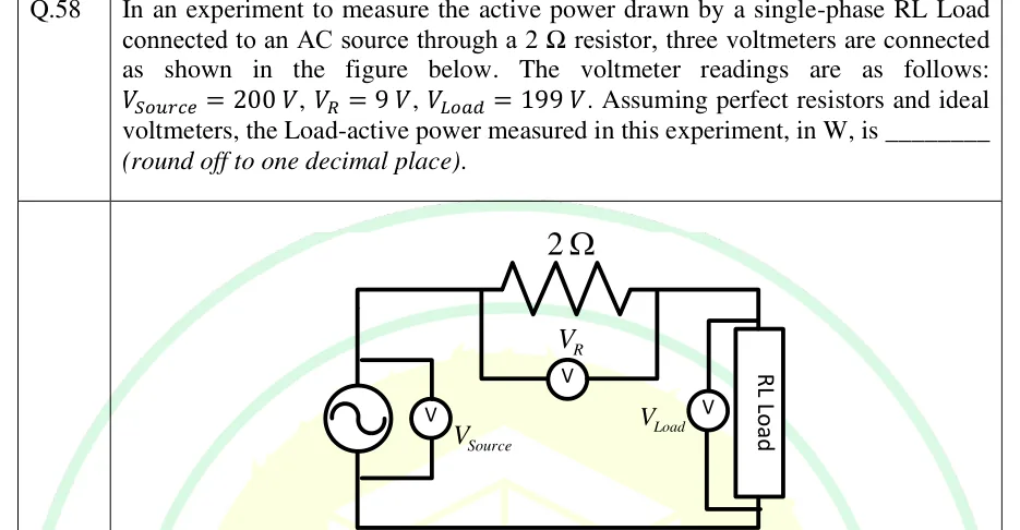
In an experiment to measure the active power drawn by a single-phase RL Load connected to an AC source through a resistor, three voltmeters are connected as shown in the figure below. The voltmeter readings are as follows: , , . Assuming perfect resistors and ideal voltmeters, the Load-active power measured in this experiment, in W, is ________ (round off to one decimal place).
GATE 2025 EE question 58: Single series loop.Tap to open full size
Figure from the GATE 2025 EE paper. It is part of the question.
Figure description

Single series loop. On the left is an AC voltage source (sine symbol in a circle) with a voltmeter labelled V_Source connected directly across its terminals. The top wire from the source passes through a 2 Ω resistor; a voltmeter labelled V_R is connected across the resistor only (its leads tap the wire on either side of the resistor). The top wire then goes to the right-hand element, a box labelled 'RL Load', with a voltmeter labelled V_Load connected directly across the load terminals. The bottom wire returns from the load to the source. So the source, the 2 Ω resistor and the RL load are in series; the three voltmeters read the source voltage, the resistor voltage and the load voltage respectively.
Answer and solution
GATE 2025 EE Q.58: answer and solution

GATE 2025 IN Q.21

GATE 2025 · INQ.21 · 1 mark · MCQ

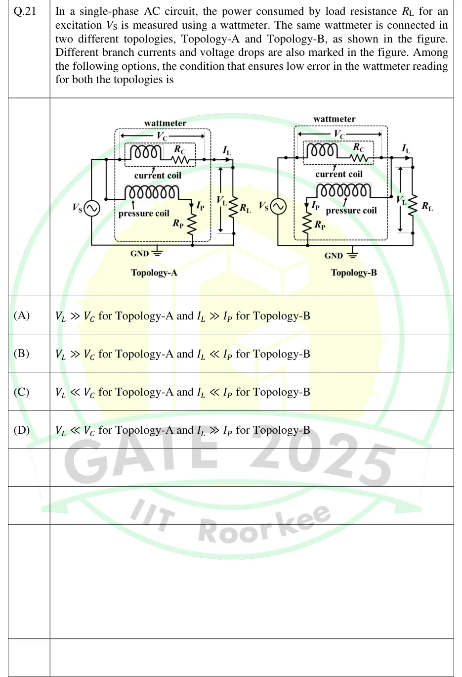
In a single-phase AC circuit, the power consumed by load resistance for an excitation is measured using a wattmeter. The same wattmeter is connected in two different topologies, Topology-A and Topology-B, as shown in the figure. Different branch currents and voltage drops are also marked in the figure. Among the following options, the condition that ensures low error in the wattmeter reading for both the topologies is

GATE 2025 IN question 21: Two circuits side by side, each with an AC source V_S on the left whose lower terminal goes to a common bottom rail marked…Tap to open full size
Figure from the GATE 2025 IN paper. It is part of the question.
Figure description

Two circuits side by side, each with an AC source V_S on the left whose lower terminal goes to a common bottom rail marked GND, and a load resistor R_L on the right between the top wire and the bottom rail. A dashed box labelled 'wattmeter' holds a current coil (inductor symbol in series with resistance R_C, in an inner dashed box labelled 'current coil') in the top wire, with the voltage across it marked V_C by a double-headed arrow spanning the coil. Below it is the pressure coil (inductor symbol) in series with resistance R_P, carrying current I_P (arrow pointing down through R_P), and the lower end of R_P goes to the bottom rail/GND. The load current I_L is marked by an arrow in the top wire just before R_L, and the voltage across R_L is marked V_L by a vertical double-headed arrow. Topology-A: the pressure-coil branch is tapped from the top wire on the SOURCE side of the current coil (left of the current coil). So the current coil carries only I_L, and the pressure coil plus R_P is across V_S = V_C + V_L. Topology-B: the pressure-coil branch is tapped from the top wire on the LOAD side of the current coil (right of the current coil, before the I_L arrow). So the pressure coil plus R_P is across V_L only, and the current coil carries I_L + I_P.

  1. (A)

    for Topology-A and for Topology-B

  2. (B)

    for Topology-A and for Topology-B

  3. (C)

    for Topology-A and for Topology-B

  4. (D)

    for Topology-A and for Topology-B

Answer and solution
GATE 2025 IN Q.21: answer and solution

GATE 2024 IN Q.60

GATE 2024 · INQ.60 · 2 marks · NAT

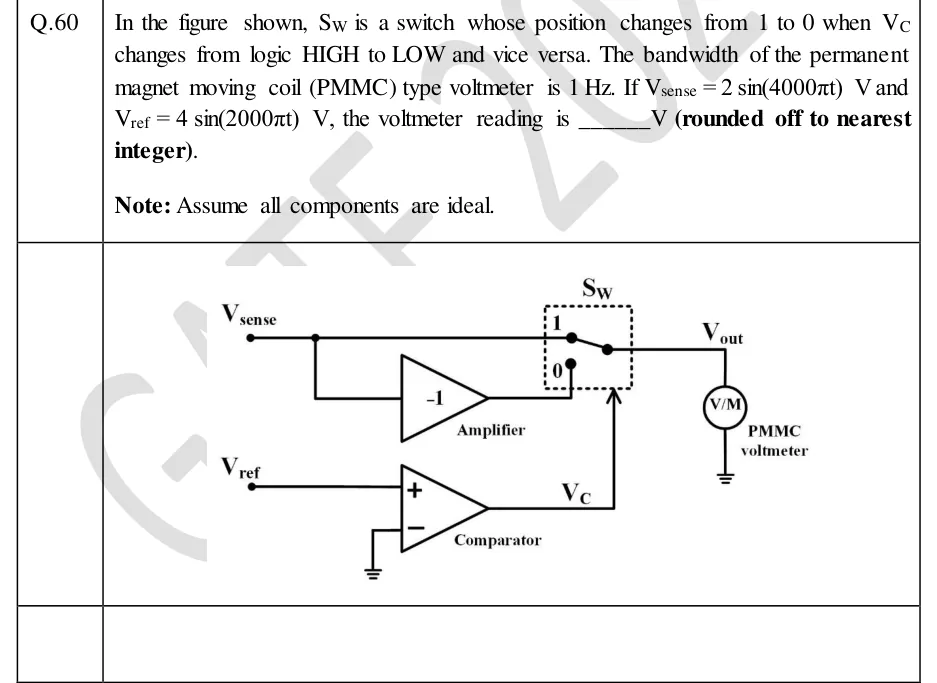
In the figure shown, is a switch whose position changes from 1 to 0 when changes from logic HIGH to LOW and vice versa. The bandwidth of the permanent magnet moving coil (PMMC) type voltmeter is . If and , the voltmeter reading is ______ (rounded off to nearest integer).

Note: Assume all components are ideal.

GATE 2024 IN question 60: The input node V_sense connects by one wire directly to terminal 1 of the switch S_W, and by a branch to the input of an…Tap to open full size
Figure from the GATE 2024 IN paper. It is part of the question.
Figure description

The input node V_sense connects by one wire directly to terminal 1 of the switch S_W, and by a branch to the input of an inverting amplifier labelled 'Amplifier' with gain -1. The amplifier output goes to terminal 0 of S_W. S_W is drawn inside a dashed box: terminal 1 at the top, terminal 0 below it, and the switch's common (pole) terminal on the right, connected to the output node V_out. V_out drives a voltmeter circle marked 'V/M', labelled 'PMMC voltmeter', whose other end is grounded. A separate input V_ref goes to the non-inverting (+) input of a comparator labelled 'Comparator'. The comparator's inverting (-) input is grounded. The comparator output V_C goes to the switch's control input, drawn as an arrow pointing up into the bottom of the dashed S_W box.

Answer and solution
GATE 2024 IN Q.60: answer and solution

GATE 2023 IN Q.34

GATE 2023 · INQ.34 · 1 mark · NAT

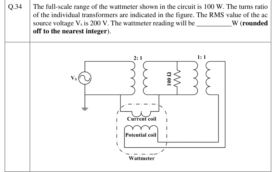
The full-scale range of the wattmeter shown in the circuit is 100 W. The turns ratio of the individual transformers are indicated in the figure. The RMS value of the ac source voltage V_s is 200 V. The wattmeter reading will be ________ W (rounded off to the nearest integer).

GATE 2023 IN question 34: An ac source V_s has its lower terminal grounded.Tap to open full size
Figure from the GATE 2023 IN paper. It is part of the question.
Figure description

An ac source V_s has its lower terminal grounded. The source is connected directly across the primary of transformer T1, turns ratio 2:1: its upper terminal goes to the top of the primary and its lower (grounded) terminal to the bottom. The secondary of T1 feeds a 100 Ω resistor and, in parallel with it, the primary of a second transformer T2 with turns ratio 1:1. The top and bottom rails of the secondary loop join the secondary, the resistor and T2's primary. A wattmeter, drawn as a dash-dot box, holds a current coil and a potential coil. The current coil's left end connects to the grounded lower wire of the source/T1-primary loop, and its right end connects to the lower wire of the T1-secondary loop. No other conductor joins the primary side to the secondary side. The potential coil sits across T2's secondary: one end goes to T2's lower secondary terminal and the other runs round to T2's upper secondary terminal. T2's secondary connects to nothing else.

Answer and solution
GATE 2023 IN Q.34: answer and solution

GATE 2023 IN Q.61

GATE 2023 · INQ.61 · 2 marks · NAT

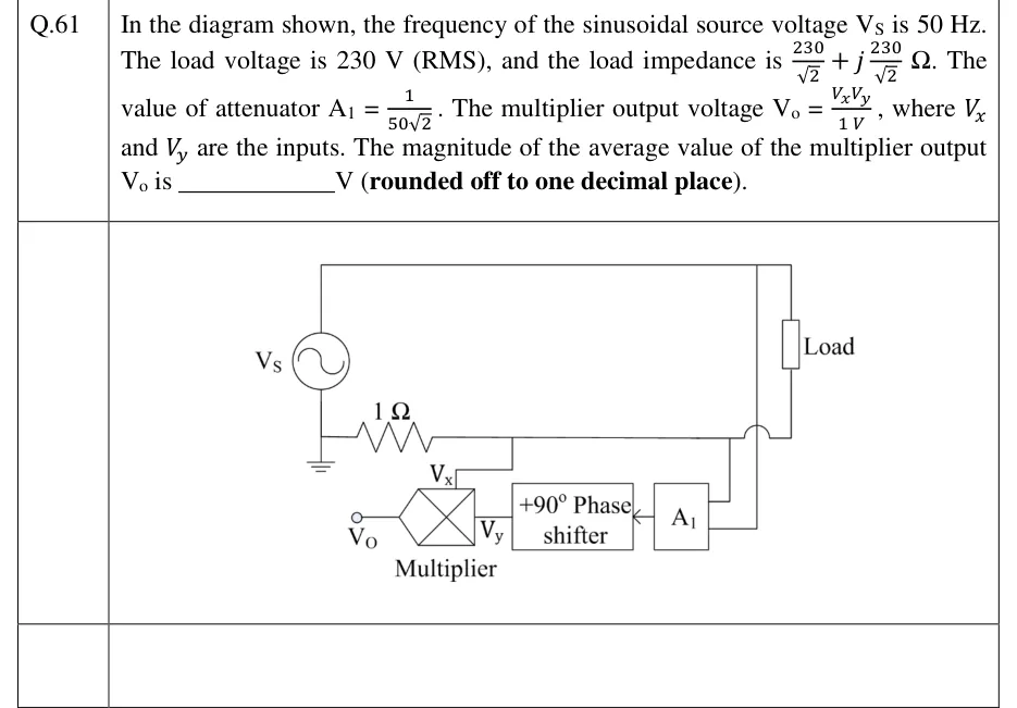
In the diagram shown, the frequency of the sinusoidal source voltage is 50 Hz. The load voltage is 230 V (RMS), and the load impedance is . The value of attenuator . The multiplier output voltage , where and are the inputs. The magnitude of the average value of the multiplier output is ________ V (rounded off to one decimal place).

GATE 2023 IN question 61: A sinusoidal source V_S on the left.Tap to open full size
Figure from the GATE 2023 IN paper. It is part of the question.
Figure description

A sinusoidal source V_S on the left. Its top terminal connects by a long top wire to the upper terminal of a box labelled 'Load' on the right. Its bottom terminal is grounded and also connects to the left end of a 1 Ω resistor drawn horizontally. The right end of the 1 Ω resistor continues as a horizontal wire that (a) has a tap going down to the V_x input of a multiplier (a box with an X in it) and (b) continues right, hopping over (not connecting to) a vertical wire, to the lower terminal of the Load. So the 1 Ω resistor is in series with the Load and carries the load current. An attenuator block A_1 has two input leads on its right: the upper lead connects to the horizontal wire at the load's lower terminal, the lower lead runs up the vertical wire (the one the horizontal wire hops over) to the top wire at the load's upper terminal; A_1 therefore senses the load voltage. The output of A_1 (arrow pointing left) feeds a block labelled '+90° Phase shifter', whose output is the V_y input of the multiplier. The multiplier output terminal on the left is labelled V_o.

Answer and solution
GATE 2023 IN Q.61: answer and solution

GATE 2018 EE Q.27

GATE 2018 · EEQ.27 · 2 marks · MCQ

A 0-1 Ampere moving iron ammeter has an internal resistance of 50 m and inductance of 0.1 mH. A shunt coil is connected to extend its range to 0-10 Ampere for all operating frequencies. The time constant in milliseconds and resistance in m of the shunt coil respectively are

  1. (A)

    2, 5.55

  2. (B)

    2, 1

  3. (C)

    2.18, 0.55

  4. (D)

    11.1, 2

Answer and solution
See the question in the paper
GATE 2018 EE Q.27: answer and solution

PRACTICE

6 questions to test yourself

PRACTICE 11 mark · MCQ

A periodic voltage is a unipolar square wave: 10 V for half of each period and 0 V for the other half. It is applied in turn to (i) a PMMC voltmeter, (ii) a moving-iron voltmeter, and (iii) a full-wave rectifier-type voltmeter (PMMC movement with a bridge rectifier and no series blocking capacitor) whose scale is calibrated to read the rms value of a sinusoid. Assuming ideal instruments, the readings (i), (ii) and (iii), in volts, are

  1. (A)

    5.00, 7.07, 5.55

  2. (B)

    5.00, 5.55, 7.07

  3. (C)

    0, 7.07, 5.55

  4. (D)

    5.00, 7.07, 7.85

Answer and solution

Answer: (A)

  1. PMMC reads the signed mean: V.

  2. Moving iron reads the rms: V.

  3. The wave never goes negative, so the mean of is 5 V. The rectifier meter reads V.

  4. Option D wrongly applies the factor 1.111 to the rms value; option C wrongly treats the wave as having zero mean.

PRACTICE 22 marks · NAT

The power drawn by a balanced three-phase, three-wire load from a balanced sinusoidal supply is measured by the two-wattmeter method. Both wattmeters deflect upscale with normal connections, and read 5.0 kW and 1.0 kW. The magnitude of the load power factor, to three decimal places, is ______.

Answer and solution

Answer: (accepted range )

  1. kW and kW.

  2. .

  3. (so ). Check with : .

PRACTICE 32 marks · NAT

A single-phase induction energy meter has a meter constant of 1500 rev/kWh. It supplies a 230 V load that draws a constant 8 A at 0.8 power factor lagging. The meter is known to register 2% more energy than is actually consumed (error expressed as a percentage of the true energy). The number of revolutions the disc makes in 15 minutes is ______.

Answer and solution

Answer: (accepted range )

  1. Power: W kW.

  2. True energy in 15 min: kWh.

  3. Registered energy: kWh.

  4. Revolutions: .

PRACTICE 42 marks · MSQ

Which of the following statements about current and voltage probes is/are correct?

  1. (A)

    A clamp-on meter based on a current transformer can measure a steady DC current in a conductor.

  2. (B)

    A Hall-effect clamp-on probe can measure both DC and AC currents without breaking the circuit.

  3. (C)

    A current-transformer clamp meter clamped around a two-core cable that carries both the live and neutral conductors of the same single-phase load reads approximately zero.

  4. (D)

    The output voltage of a Rogowski coil is proportional to the rate of change of the enclosed current, so an integrator is needed to indicate the current.

Answer and solution

Answer: (B), (C), (D)

  1. A is false: a steady DC current produces a steady flux, which induces no EMF, so there is no transformer action.

  2. B is true: the Hall voltage is proportional to the flux in the core gap, which is proportional to the conductor current, for DC and AC alike.

  3. C is true: the live and neutral currents are equal and opposite, so the net current through the jaws is close to zero.

  4. D is true: the air-cored coil gives , which must be integrated to recover .

PRACTICE 51 mark · NAT

A wattmeter whose pressure-coil circuit has a resistance of 5 kΩ (inductance negligible) is connected with its pressure coil directly across the load terminals, so that its current coil carries both the load current and the pressure-coil current. The load voltage is 250 V and the wattmeter reads 1012.5 W. Neglecting all other errors, the true power consumed by the load, in watts, is ______.

Answer and solution

Answer: (accepted range )

  1. In this connection the reading includes the pressure-coil loss: .

  2. W.

  3. W.

PRACTICE 62 marks · NAT

The voltage across a load is V and the current through it is A. The reading of an ideal electrodynamometer wattmeter (pressure-coil inductance negligible) measuring the power drawn by the load, in watts, rounded to the nearest watt, is ______.

Answer and solution

Answer: (accepted range )

  1. Only components of the same frequency contribute: , with rms values.

  2. Fundamental: W.

  3. Third harmonic: the current leads the voltage by , so W.

  4. W.

OFFICIAL GATE 2027 SYLLABUS WORDING

Copied from the GATE 2027 syllabus; see all 2027 syllabi.

GATE EE

Measurement of voltage, current, power, energy and power factor

GATE IN

measurement of voltage, current and power in DC, single and three phase AC circuits; contact and noncontact type AC and DC current and voltage probes; true rms meters, voltage and current scaling

Preparing in Kolkata? IAE Academy's course for GATE EE or GATE IN.