
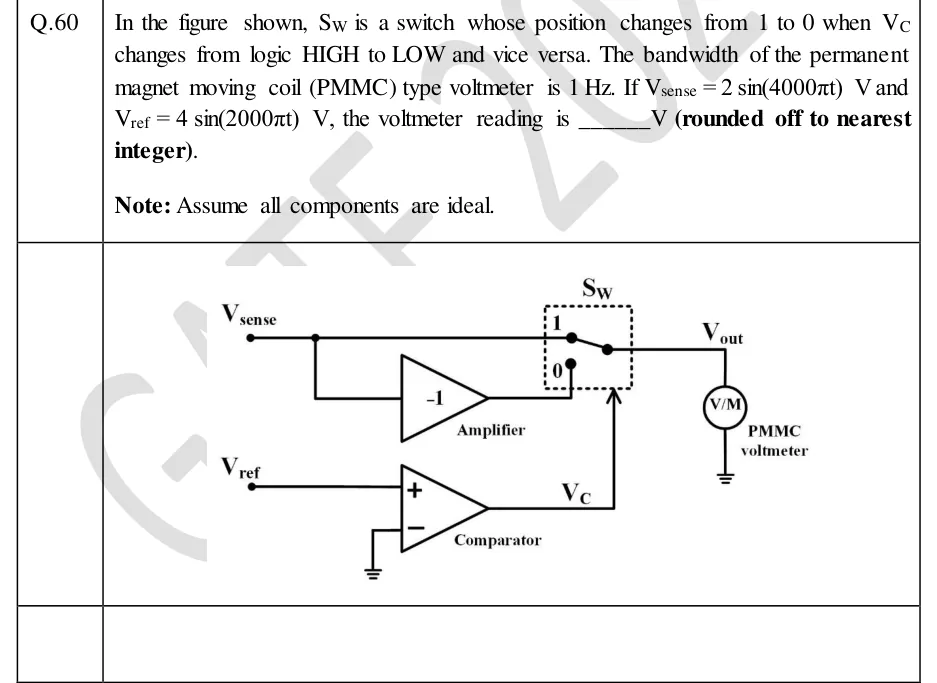
In the figure shown, is a switch whose position changes from 1 to 0 when changes from logic HIGH to LOW and vice versa. The bandwidth of the permanent magnet moving coil (PMMC) type voltmeter is . If and , the voltmeter reading is ______ (rounded off to nearest integer).
Note: Assume all components are ideal.
 Tap to open full size
Figure description
The input node V_sense connects by one wire directly to terminal 1 of the switch S_W, and by a branch to the input of an inverting amplifier labelled 'Amplifier' with gain -1. The amplifier output goes to terminal 0 of S_W. S_W is drawn inside a dashed box: terminal 1 at the top, terminal 0 below it, and the switch's common (pole) terminal on the right, connected to the output node V_out. V_out drives a voltmeter circle marked 'V/M', labelled 'PMMC voltmeter', whose other end is grounded. A separate input V_ref goes to the non-inverting (+) input of a comparator labelled 'Comparator'. The comparator's inverting (-) input is grounded. The comparator output V_C goes to the switch's control input, drawn as an arrow pointing up into the bottom of the dashed S_W box.