GATE 2025 IN Q.23
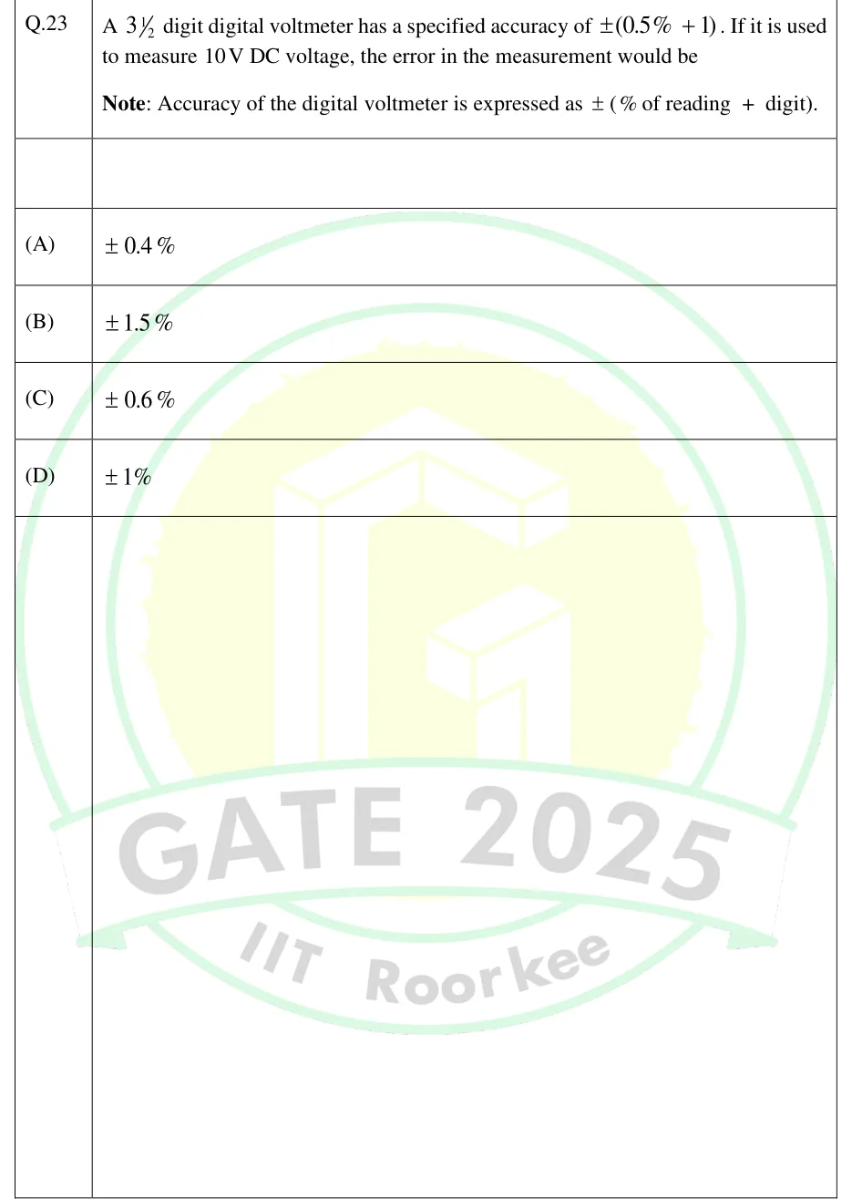
A digit digital voltmeter has a specified accuracy of . If it is used to measure DC voltage, the error in the measurement would be
Note: Accuracy of the digital voltmeter is expressed as (% of reading + digit).
- (A)
- (B)
- (C)
- (D)

GATE EE · IN
A digital voltmeter converts an analog voltage into a count of clock pulses or code steps and shows it on a decimal display. It is described by its digits and counts, which set its resolution and sensitivity, by an accuracy specification written as a percentage of reading plus a number of counts, and by its conversion principle: ramp, dual-slope integrating, voltage-to-frequency, successive approximation or flash. Typical numerical problems ask you to find a meter's resolution or sensitivity, turn an accuracy specification into a worst-case error on a particular range, work through a dual-slope conversion, or compare converter types. The digital multimeter puts signal conditioning in front of the same kind of converter to measure current, resistance and ac quantities, and the digital energy meter samples voltage and current, multiplies the samples and accumulates energy.
2 previous-year questions · 2 solved · 6 practice questions
A digital voltmeter (DVM) turns an analog voltage into a number of counts and shows it on a decimal display. A full digit can show 0 to 9. A half digit is a leading position that can show only 0 or 1. An N½-digit display has N full digits plus that half digit. A 3½-digit display therefore runs from 0000 to 1999, which is 2000 different readings, so it is also called a 2000-count display. Convention used in these notes: in '3½ digit', N = 3, because N counts only the full digits.
One count is one step of the least significant (rightmost) digit. How many volts one count is worth depends on the range, because the range sets where the decimal point sits. On a 3½-digit meter, the range that reads up to 1.999 V has 1 count = 1 mV, and the range that reads up to 19.99 V has 1 count = 10 mV. In the classical convention these are called the 1 V and 10 V ranges, and the half digit is said to give nearly 100% overrange. Manufacturers usually label the same ranges 2 V and 20 V. One count is worth the same under either label. If the input is larger than the maximum display, the meter shows an overload indication instead of a number. Many 3½-digit meters show a lone '1' or 'OL'.
RESOLUTION OF AN N½-DIGIT DISPLAY
N is the number of full digits, so for 3½ digits N = 3 and R = 0.001. R is the smallest step as a fraction of the decade range. The half digit adds overrange, not resolution.
COUNTS OF AN N½-DIGIT DISPLAY
3½ digit: 2000 counts, maximum display 1999. 4½ digit: 20000 counts, maximum 19999. A plain N-digit display has counts.
VALUE OF ONE COUNT (ONE 'DIGIT') ON A RANGE
This is the place value of the last displayed digit. Use the first form when ranges are named by decade (1 V, 10 V, ...). Use the second when they are named by full count (2 V, 20 V, ... on a 2000-count meter).
SENSITIVITY OF A DVM
is the full scale of the lowest range, taken at its decade value. For example, a range that reads up to 199.9 mV counts as 100 mV. S is the smallest change in input the meter can display at all, and it equals the place value of the last digit on the lowest range.
Display | Maximum display | Counts | Resolution | One count on the 1 V decade range |
|---|---|---|---|---|
3 digit | 999 | 1000 | 1 mV (reads to 0.999 V) | |
3½ digit | 1999 | 2000 | 1 mV (reads to 1.999 V) | |
4½ digit | 19999 | 20000 | 0.1 mV (reads to 1.9999 V) | |
5½ digit | 199999 | 200000 | 10 μV (reads to 1.99999 V) |
EXAM TIP
Resolution is not accuracy. A 4½-digit meter shows 0.1 mV steps on its 1.9999 V range. If its accuracy is ±(0.1% of reading + 2 counts), a 1 V reading is uncertain by ±(1 mV + 0.2 mV) = ±1.2 mV, so the last digit cannot be trusted on its own.
EXAM TIP
Labels such as '3¾ digit' are not used the same way by all manufacturers. If a question gives the count or the maximum display, work from that and not from the label.
A DVM's accuracy is quoted as a limiting error: a guaranteed bound on the difference between the displayed value and the true value. The bound has two parts:
Some instruments give the second part as a percentage of the range (full scale) instead. On a given range that is also a fixed voltage.
Convention used in these notes: 'reading' means the displayed value, and a DVM's limiting error is expressed as a percentage of that reading, because the true value is not known. Where an error below is taken relative to the true value instead (the loading error, the waveform error of an average-responding meter, the error of an energy meter), the notes say so.
LIMITING ERROR FOR ±(A% OF READING + M COUNTS)
is the value of one count on the range in use. The two terms are added because this is a worst-case bound.
LIMITING ERROR AS A PERCENTAGE OF READING
The count term is fixed in volts, so the percentage error rises as the reading falls.
LIMITING ERROR FOR ±(A% OF READING + B% OF RANGE)
On a given range, the b% of range (full scale) term is a fixed voltage, just like the counts term. As a percentage of reading this is .
Identify N and the range in use. Find , the place value of the last digit on that range.
Compute the reading term: .
Compute the count term: (or ).
Add the two for the worst-case . Divide by the reading and multiply by 100 for the percentage error.
If asked which range to use, repeat the calculation on every range that does not overrange. When the specification is the same on every range, the lowest such range gives the smallest error, because its count is worth the least. When the specification differs from range to range, compare the totals.
WORKED EXAMPLE
A 4½-digit DMM has dc voltage ranges that read up to 1.9999 V and up to 19.999 V. On both ranges its dc accuracy is ±(0.05% of reading + 3 counts). It is used to measure a 1.5 V source of negligible source resistance. Find the limiting error on each range, in volts and as a percentage of the reading, and say which range should be used.
1.9999 V range. The last digit is in the 0.1 mV place, so 1 count = 0.1 mV. The display shows 1.5000 V.
Reading term = 0.05% × 1.5000 V = 0.75 mV. Count term = 3 × 0.1 mV = 0.30 mV. So mV, which is of reading.
19.999 V range. Here 1 count = 1 mV, and the display shows 1.500 V (01.500).
Reading term = 0.75 mV, the same as before. Count term = 3 × 1 mV = 3 mV. So mV, which is ±0.25% of reading.
The count term is ten times larger on the higher range. Use the lowest range that does not overrange, the 1.9999 V range. On that range the true value lies between 1.49895 V and 1.50105 V.
Answer: 1.9999 V range: ±1.05 mV (±0.07% of reading). 19.999 V range: ±3.75 mV (±0.25% of reading). Use the 1.9999 V range.
EXAM TIP
'±1 digit' in a specification means ±1 count of the least significant digit. It does not mean ±1 in the leading digit, and it does not mean ±1%.
EXAM TIP
Watch low readings. Take a 3½-digit meter with accuracy ±(0.5% of reading + 1 digit) on its 1.999 V range. A reading of 1.000 V has error ±(5 + 1) mV = ±6 mV, or 0.6%. A reading of 0.100 V on the same range has error ±(0.5 + 1) mV = ±1.5 mV, or 1.5% of reading.
Single-slope (linear ramp) DVM. At the start of a measurement the meter generates a linear ramp of known slope. One comparator fires when the ramp crosses the input voltage, and a second fires when the ramp crosses zero. During the interval between the two firings, a gate passes clock pulses to a counter, so the count is proportional to . The meter reads the input's instantaneous value at the crossing, so any noise on the input goes straight into the reading. Its accuracy depends on the ramp's slope and linearity, which are set by an RC product, on the two comparators, and on how stable the clock is.
SINGLE-SLOPE RAMP DVM
is the ramp slope in V/s and is the clock frequency. Both must be accurate and stable, because nothing cancels them and nothing averages out noise.
Dual-slope integrating DVM. This type measures the average of the input over a fixed time instead of its instantaneous value. It uses an op-amp integrator, whose output is , twice in each conversion: first on the input, then on a reference of opposite polarity. The answer comes from the ratio of the two counted times.
Auto-zero / reset: the integrator capacitor is discharged and the counter is cleared. Many designs also measure and store the integrator and comparator offsets here so that they can be cancelled.
Run-up (signal integration): is applied to the integrator for a fixed time , during which the counter counts a fixed pulses. The inverting integrator's output ramps to , a magnitude proportional to .
Run-down (de-integration): the input is switched to a reference of opposite polarity, for a positive . The output returns towards zero at a fixed slope . The counter counts pulses until the zero-crossing detector fires.
Display: the meter shows . If is a power of ten per volt, reads directly in volts. For example, with V gives 1000 counts per volt.
DUAL-SLOPE BALANCE
Use magnitudes; and have opposite polarity. For an input that varies during run-up, here is its average over . R, C and cancel as long as they stay constant for one conversion, so the only component value the reading depends on is . The integrator, switches and comparator must still behave ideally (linear and free of offset), and the result is quantised to ±1 count.
PEAK INTEGRATOR OUTPUT
Assumes a dc input and an integrator that starts from 0 V. At full-scale input this must stay inside the op-amp's output swing, which sets the smallest usable RC.
DUAL-SLOPE CONVERSION TIME
For a dc input. Add any auto-zero time on top. Integrating DVMs are slow compared with successive-approximation and flash converters, because is usually one or more periods of the power-line frequency.
NORMAL-MODE REJECTION OF AN INTEGRATING DVM
Assumes a sinusoidal interference of frequency f added to the input, and a reading equal to the average of the input over . NMRR is the ratio of the peak interference to the worst-case error it causes in that average. It is infinite (ideal rejection) when is a whole number, that is, when is an integer multiple of the interference period.
WORKED EXAMPLE
A dual-slope DVM has a 100 kHz clock and a fixed run-up of clock periods. Its reference has magnitude 2.000 V, and its integrator has R = 100 kΩ and C = 0.2 μF, starting from 0 V. A dc input of +1.234 V is applied. Find (a) the run-down count and the time , (b) the peak integrator output, (c) the conversion time excluding auto-zero, (d) the normal-mode rejection at 50 Hz and at 60 Hz, and (e) the reading and the 50 Hz rejection if the clock ran at a steady 90 kHz instead.
ms, and ms.
(a) counts, and ms. At 1000 counts per volt, the display reads 1.234 V directly.
(b) V. The output is negative, because an inverting integrator is fed a positive input.
(c) ms.
(d) At 50 Hz, and , so NMRR is infinite (ideal rejection). At 60 Hz, , so NMRR , and dB.
(e) At 90 kHz, ms and ms, so and the reading is unchanged. However, is no longer a whole number of 50 Hz periods: , so NMRR , about 20.2 dB. The ideal 50 Hz rejection is lost.
Answer: (a) = 1234, = 12.34 ms. (b) 1.234 V in magnitude. (c) 32.34 ms. (d) Ideal (infinite) at 50 Hz; 6.41 (16.1 dB) at 60 Hz. (e) Still 1.234 V, but the 50 Hz NMRR falls to 10.2 (about 20.2 dB).
EXAM TIP
R, C and the clock cancel only within one conversion. A slow drift between conversions does no harm; a change during run-up or run-down does. The reference voltage never cancels.
EXAM TIP
For 50 Hz interference, any of 20 ms, 40 ms, 60 ms, ... gives ideal rejection. = 100 ms rejects both 50 Hz and 60 Hz, because it spans exactly 5 and 6 cycles.
EXAM TIP
Integration rejects normal-mode (series-mode) interference, which appears between the two input terminals in series with the signal. Common-mode interference appears on both terminals relative to ground. It is reduced by a differential, floating and guarded input, not by integrating.
COMMON-MODE REJECTION RATIO
is the common-mode voltage applied between both input terminals and ground, and is the error it produces in the reading, expressed as an equivalent input voltage. Instrument specifications state it with a stated source-resistance imbalance in one input lead, because the imbalance is what turns a common-mode voltage into a normal-mode error.
Successive approximation (SAR). An n-bit SAR converter tests one bit at a time, starting from the MSB. It sets the bit, compares the DAC output with , and keeps the bit if the DAC output is not greater than ; otherwise it clears the bit. It needs one comparator and one DAC, and every conversion takes n clock periods whatever the input. Because it effectively samples the input, the input must not change by more than about ½ LSB during a conversion. In practice a sample-and-hold circuit holds it steady. The SAR DVM is a potentiometric (null-balance) DVM: it balances the input against an internally generated reference voltage, adjusted in binary steps.
Worked trial sequence: a 4-bit SAR with = 16 V (so 1 LSB = 1 V) converting = 11.3 V.
Try 1000: DAC = 8 V ≤ 11.3 V, so keep the bit.
Try 1100: DAC = 12 V > 11.3 V, so clear it, leaving 1000.
Try 1010: DAC = 10 V ≤ 11.3 V, so keep the bit.
Try 1011: DAC = 11 V ≤ 11.3 V, so keep the bit. The result is 1011 = 11 V after 4 clock periods. Used this way, the converter truncates: the result is between 0 and 1 LSB below . Offsetting the DAC by ½ LSB makes it round instead, with error ±½ LSB.
ADC RESOLUTION (SIZE OF 1 LSB)
is the full-scale input range. Some treatments use because they define the top code as equal to ; use whichever definition the question gives. An ideal rounding converter has quantisation error ±½ LSB.
SAR CONVERSION TIME
This is fixed and does not depend on . Some designs add start or end-of-conversion clock cycles on top.
Staircase-ramp (counter-type) converter. The analog ramp is replaced by a DAC driven by the counter. Counting stops when the staircase passes , so the conversion time depends on the input.
Flash converter. It compares with every threshold at once, using a resistor ladder and comparators, then encodes the result. It is the fastest type, but the number of comparators roughly doubles with every extra bit. It therefore suits digital oscilloscopes and high-speed data acquisition rather than precision voltmeters.
Voltage-to-frequency DVM. It converts into a pulse train whose rate is proportional to and counts the pulses over a fixed gate time. Like the dual-slope type, it integrates the input, so noise averages out.
STAIRCASE (COUNTER) RAMP: WORST-CASE CONVERSION TIME
The conversion time varies with . A full-scale input takes the longest.
FLASH ADC HARDWARE
All comparisons happen in parallel, so a conversion takes one clock period. An 8-bit flash converter needs 255 comparators.
VOLTAGE-TO-FREQUENCY DVM
k is the V/f conversion gain in Hz/V and is the gate time. The count formula holds for a dc input; for a varying input the count is times the integral of over . Because the reading is an integral over , choosing as a whole number of interference periods rejects that interference.
Type | How it converts | Conversion time | Noise rejection | Accuracy depends on |
|---|---|---|---|---|
Single-slope ramp | Counts clock pulses while an analog ramp travels between 0 and | Proportional to | Poor: reads the instantaneous value | Ramp slope and linearity (RC), comparators, clock frequency |
Staircase (counter) ramp | A counter drives a DAC until the staircase passes | Varies with , up to | Poor | DAC and comparator |
Dual-slope integrating | Integrates for a fixed , de-integrates , counts | : slow | Very good for normal-mode interference; ideal when is an integer | (RC and clock cancel within a conversion) |
Voltage-to-frequency | sets a pulse rate, counted over a fixed gate time | Gate time | Good: integrating | V/f linearity, gate time |
Successive approximation | Binary search with one comparator and a DAC, MSB first | , fixed | None built in; needs sample-and-hold | DAC, comparator, |
Flash (parallel) | comparators against a resistor ladder, all at once | One clock period: the fastest | None | Ladder matching, comparator offsets |
EXAM TIP
Count comparators carefully. A SAR converter uses one. A dual-slope converter uses one (the zero-crossing detector). The single-slope ramp DVM described above uses two (input and ground comparators). A flash converter uses .
EXAM TIP
Most precision bench and handheld DVMs use integrating converters. They give up speed in return for noise rejection, and for an accuracy that depends on the reference rather than on R, C or the clock.
A digital multimeter (DMM) is a DVM, commonly built on an integrating converter with a 3½- to 6½-digit display, with signal conditioning in front of it. Each function turns its quantity into a dc voltage within the ADC's range. The same digits, counts and accuracy rules then apply, but each function and range has its own accuracy specification.
Function | Conditioning before the ADC | What limits accuracy / what to watch |
|---|---|---|
DC voltage | A precision resistive divider (attenuator) selects the range. The input resistance is high, typically about 10 MΩ, and on many meters it is the same on every range (unlike an analog voltmeter, whose input resistance is its ohms-per-volt figure times the range) | Loading of high-resistance sources |
AC voltage | Attenuator, then an ac-to-dc converter: either average-responding (a rectifier scaled to read the rms of a sine) or true-rms | Waveform shape (average-responding); crest factor and bandwidth (true-rms) |
DC current | The current flows through a known shunt, and the voltage is measured | Burden voltage inserted into the circuit |
AC current | Shunt followed by an ac-to-dc converter | Burden voltage and waveform shape |
Resistance | A known constant current is forced through , and is measured | Lead resistance on low ranges (use 4-wire connection); test current |
Diode test / continuity | Diode test: a small constant current is applied and the display shows the voltage across the device. Continuity: a beeper sounds below a threshold resistance | The diode-test reading is the junction forward voltage at that test current |
LOADING ERROR ON THE DC VOLTAGE FUNCTION
The source is modelled as its Thevenin equivalent (, ), and is the DMM's input resistance. The error is taken relative to the true (unloaded) voltage . It is negative: the meter always reads low.
CURRENT FUNCTION: BURDEN
The circuit is modelled as a source in series with its total resistance , and is the current with the meter in place. The shunt adds in series with the circuit, so in a low-resistance circuit a large burden reduces the very current being measured.
RESISTANCE FUNCTION
Assumes a constant-current source . With a 4-wire connection, one pair of leads carries and the other senses , so lead resistance drops out.
AVERAGE-RESPONDING METER, CALIBRATED IN RMS OF A SINE WAVE
is the full-wave rectified average of the actual waveform. The indication equals the true rms only for a sinusoid, because 1.11 is the sine form factor. A half-wave average-responding meter instead multiplies the half-wave average by ; it too is correct only for a sine.
WAVEFORM ERROR OF AN AVERAGE-RESPONDING METER
is the true rms of the actual waveform, so this error is relative to the true value. is 1.11 for a sine, 1 for a square wave and for a triangle wave. So a square wave reads 11.1% high and a triangle wave reads about 3.8% low.
TOTAL RMS OF A WAVEFORM WITH A DC COMPONENT
An ac-coupled true-rms meter shows only . To get the total rms, combine it with the dc reading as shown.
EXAM TIP
To find what an average-responding meter shows for a non-sinusoidal waveform, compute that waveform's full-wave rectified average and multiply it by 1.11. Never assume the meter shows the true rms.
EXAM TIP
A true-rms meter is specified up to a maximum crest factor, . The crest factor is for a sine, 1 for a square wave and for a triangle wave. Narrow pulses have large crest factors and can exceed the meter's rating.
A digital (static) energy meter has no moving parts. It samples voltage and current, multiplies the samples, and adds up the products over time. It works for any waveform shape within its bandwidth, which its sampling rate and input filters set, and the same data give it rms values, power factor and other quantities.
Voltage sensing: a resistive divider scales the line voltage down to the ADC's input range.
Current sensing: a shunt, CT or Hall-effect sensor gives a voltage proportional to . A Rogowski coil gives a voltage proportional to , which is integrated to recover .
Sampling: two ADC channels sample and at the same instant, or with a known delay that is compensated. The sampling rate must be more than twice the highest harmonic frequency to be measured ().
Processing: a DSP or metering IC multiplies each pair of samples to get instantaneous power and accumulates the products to get energy. It also computes , , active power and power factor, and often reactive energy and maximum demand.
Output: each time the accumulated energy passes a fixed quantum of kWh, the meter emits one pulse on its calibration LED or pulse output and advances the kWh register.
Analog-multiplier designs: some electronic meters use an analog multiplier followed by a voltage-to-frequency converter. The pulse rate is then proportional to power, which gives the same pulses-per-kWh behaviour.
ACTIVE POWER FROM SAMPLES
The samples must span a whole number of cycles; otherwise the reading ripples. It stays correct when harmonics are present, provided the sampling rate satisfies .
ENERGY ACCUMULATION
is the sampling interval. Energy is the running sum of instantaneous power × time.
RMS VALUES AND POWER FACTOR FROM SAMPLES
is the apparent power S. For sinusoidal v and i, PF = cos φ, where φ is the angle between them.
METER CONSTANT: PULSES AND ENERGY PER PULSE
C is the meter constant in impulses per kWh (imp/kWh). For example, C = 3200 imp/kWh gives 0.3125 Wh (1125 J) per pulse.
PULSE RATE AT CONSTANT POWER
P is the active power in kW and C is in imp/kWh.
PERCENTAGE ERROR OF AN ENERGY METER
Error is taken relative to the true energy. It is positive when the meter over-registers. in kWh.
EXAM TIP
Suppose the voltage and current channels have a small uncompensated relative phase shift δ (in radians). The meter then computes instead of , a fractional error of about . This is negligible at unity power factor and large at low power factor. For example, δ = 0.1° = 1.745 mrad at pf 0.5 ( = 1.732) gives an error of about 0.30%.
EXAM TIP
Although the meter has no disc, two tests still apply in electronic form. In the starting test, the meter must begin registering at a specified small current. In the no-load (anti-creep) test, it must not keep emitting pulses when voltage is applied and no load current flows.
PREVIOUS-YEAR QUESTIONS
Try each question first, then open the answer. We placed each question under a topic ourselves; the exam paper does not label topics.
See these papers in full: GATE IN 2025 · GATE IN 2023
A digit digital voltmeter has a specified accuracy of . If it is used to measure DC voltage, the error in the measurement would be
Note: Accuracy of the digital voltmeter is expressed as (% of reading + digit).
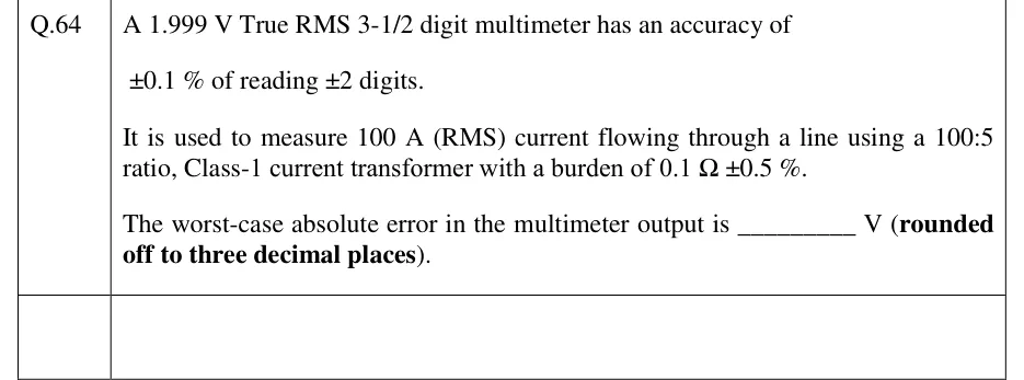
A 1.999 V True RMS 3-1/2 digit multimeter has an accuracy of
of reading digits.
It is used to measure 100 A (RMS) current flowing through a line using a 100:5 ratio, Class-1 current transformer with a burden of .
The worst-case absolute error in the multimeter output is ________ V (rounded off to three decimal places).
PRACTICE
A 4½-digit DVM (maximum display 19999) has a lowest range that reads up to 199.99 mV. The smallest change in input voltage that this meter can display is
1 μV
10 μV
20 μV
100 μV
Answer: (B)
A 4½-digit display has N = 4 full digits, so .
The lowest range reads up to 199.99 mV, so its decade value is 100 mV. Then mV = 10 μV.
Check: the last digit of 199.99 mV is in the 0.01 mV place. The trap is to multiply 200 mV by and get 20 μV; the display has no 20 μV step.
A 3½-digit DMM is set to its range that reads up to 199.9 V. Its accuracy on this range is ±(0.8% of reading + 2 counts). It displays 50.0 V. The limiting error, expressed as a percentage of the reading, is ______ %.
Answer: (accepted range )
On the range that reads up to 199.9 V, the last digit is in the 0.1 V place, so 1 count = 0.1 V.
Reading term = 0.8% × 50.0 V = 0.40 V. Count term = 2 × 0.1 V = 0.20 V.
V, which is of reading.
A dual-slope integrating DVM uses a 200 kHz clock. A positive dc input is integrated for exactly 4000 clock periods, with the integrator output starting from 0 V. The integrator is then switched to a reference of magnitude 2.500 V and opposite polarity, and 2960 clock periods pass before its output returns to zero. The integrator time constant is RC = 25 ms. The magnitude of the peak integrator output voltage, in volts, is ______.
Answer: (accepted range )
ms.
V.
V.
Check with the run-down: ms, and V.
Which of the following statements about digital voltmeter converters is/are correct?
The reading of a dual-slope DVM does not depend on the exact values of the integrator R and C or of the clock frequency, provided they stay constant during a conversion.
An 8-bit successive-approximation converter needs 255 comparators.
If the fixed integration period of a dual-slope DVM is exactly 40 ms, normal-mode interference at 50 Hz is ideally rejected.
A single-slope ramp DVM rejects noise superimposed on the input, because its reading is the average of the input over the ramp time.
Answer: (A), (C)
A: correct. , so RC and cancel within one conversion.
B: wrong. A SAR converter uses one comparator and a DAC. It is an 8-bit flash converter that needs comparators.
C: correct. , a whole number, so and the NMRR is infinite.
D: wrong. The single-slope ramp DVM reads the instantaneous input at the moment the ramp crosses it, so it averages nothing. Integrating types (dual-slope, V/f) are the ones that reject noise.
A single-phase digital energy meter has a meter constant of 3200 imp/kWh. It supplies a load drawing 5 A at 230 V and 0.9 power factor lagging (sinusoidal voltage and current, all constant) for 20 minutes. During this time its pulse output delivers 1110 pulses. The percentage error of the meter, taken relative to the true energy and positive when the meter over-registers, is ______ %.
Answer: (accepted range )
True power: W.
True energy: Wh = 0.345 kWh.
Expected pulses: .
Error: (over-registering).
An average-responding digital multimeter, calibrated to read the rms value of a sine wave, is set to its ac voltage function and connected to a symmetrical square wave that alternates between +10 V and −10 V (zero mean). The value the meter displays, in volts, is ______.
Answer: (accepted range )
The full-wave rectified square wave is a steady 10 V, so V.
The meter shows V.
Check: the true rms of this square wave is 10 V (), so the meter reads times the true rms, which is 11.1% high.
OFFICIAL GATE 2027 SYLLABUS WORDING
Copied from the GATE 2027 syllabus; see all 2027 syllabi.
GATE EE
Digital voltmeters and multi-meters
GATE IN
digital voltmeter, digital multimeter, digital energy meter
Preparing in Kolkata? IAE Academy's course for GATE EE or GATE IN.