
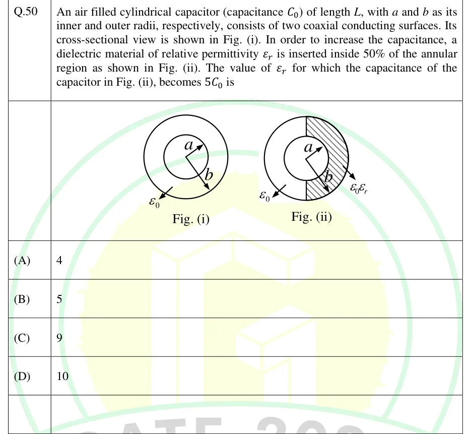
An air filled cylindrical capacitor (capacitance ) of length , with and as its inner and outer radii, respectively, consists of two coaxial conducting surfaces. Its cross-sectional view is shown in Fig. (i). In order to increase the capacitance, a dielectric material of relative permittivity is inserted inside 50% of the annular region as shown in Fig. (ii). The value of for which the capacitance of the capacitor in Fig. (ii), becomes is
 Tap to open full size
Figure description
Two cross-sections of a coaxial cylindrical capacitor. Fig. (i): two concentric circles. The inner circle has radius a and the outer circle radius b, each shown by an arrow from the common centre (a towards the upper right, b towards the lower right). An arrow labelled epsilon_0 points into the annular region between them, which is air. Fig. (ii): the same two concentric circles of radii a and b. The annulus is split along the vertical diameter by two line segments: one from the top of the inner circle to the top of the outer circle, and one from the bottom of the inner circle to the bottom of the outer circle. The left half-annulus is unshaded, with an arrow labelled epsilon_0 pointing into it. The right half-annulus is hatched, with an arrow labelled epsilon_0 epsilon_r pointing into it. So the dielectric fills the right angular half of the annulus (phi from -pi/2 to pi/2, measured from the rightward horizontal) across the full radial gap from a to b.
- (A)
4
- (B)
5
- (C)
9
- (D)
10