
IAE Academy

GATE 2026 EE Q.46: solution and answer

GATE 2026 · EEQ.46 · 2 marks · MCQ

The MOSFET switches shown in the circuit are ideal.

[Figure]

Which of the following is the correct option for Boolean logical expression of the output (OUT), and the maximum possible power (P) consumed by the circuit?
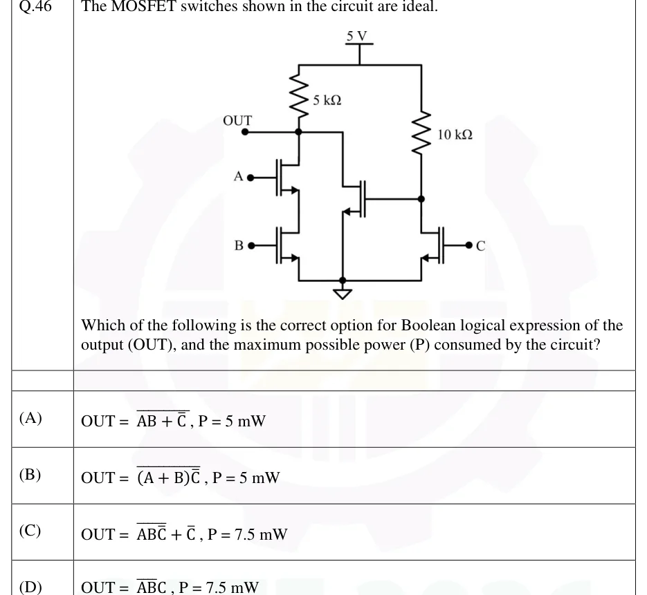
GATE 2026 EE question 46: A 5 V supply feeds two resistive-load branches.Tap to open full size
Figure from the GATE 2026 EE paper. It is part of the question.
Figure description

A 5 V supply feeds two resistive-load branches. All four transistors are n-channel enhancement MOSFETs (ideal switches), and every source goes to one common ground. Left branch: a 5 kΩ resistor runs from 5 V down to node OUT, which is brought out as the output terminal. Below OUT are two NMOS in series: M_A (gate = input A) has its drain at OUT and its source tied to the drain of M_B (gate = input B), and M_B's source goes to ground. Right branch: a 10 kΩ resistor runs from 5 V down to an internal node X. NMOS M_C (gate = input C) has its drain at X and its source at ground. Middle transistor: NMOS M_X has its drain wired to node OUT, its gate wired to node X and its source at ground, so M_X is in parallel with the series pair M_A–M_B.

  1. (A)

    ,

  2. (B)

    ,

  3. (C)

    ,

  4. (D)

    ,

Answer and solution

ANSWER

The answer is (D): and , reached at .

Official answer: DSource: Official answer key, GATE 2026 EE (IIT Guwahati)

  1. Right branch: a resistive-load NMOS inverter. When , turns on and pulls node to 0. When , is off. No current then flows through the 10 kΩ resistor, because a MOSFET gate draws none, so . Hence (an overbar means complement throughout).

  2. Left branch: a pull-down network under a 5 kΩ load. Switches in series give AND, and switches in parallel give OR. OUT is pulled low when both and conduct (), or when conducts (). Otherwise no current flows and the 5 kΩ resistor pulls OUT high.

  3. So

  4. De Morgan: . This is exactly the expression in (A) and in (D), so the power figure has to decide between them. (C) reduces to , a constant, so it is wrong. (B) fails at : the circuit gives (here is on), but (B) gives .

  5. Power in each branch, with ideal switches (): a branch draws when its pull-down path conducts, and nothing otherwise. The right branch draws , only when . The left branch draws whenever OUT is pulled low, whether through one path or both, because the 5 kΩ resistor alone sets the current.

  6. Which inputs maximise P? If , then is on: the left branch takes 5 mW and the right branch takes 0, a total of 5 mW. If , then is off; with the series pair conducts, so the left branch takes 5 mW and the right branch takes 2.5 mW.

  7. and . That rules out (A), which has the right expression but 5 mW, and the answer is option (D).

KEY IDEA

Treat each resistive-load NMOS stage as a pull-down network: series switches give AND, parallel switches give OR, and the output is the complement of that. The right stage makes , which drives in parallel with the – series pair, so . With ideal switches, a branch dissipates only while its pull-down path conducts. Both branches can conduct at once only when and , which gives .

WATCH OUT FOR

The usual slip is to stop once the Boolean expression is found. Option (A) is the same expression as (D), written before applying De Morgan, so you can only separate them by working out the power. The other trap is the power itself: taking the case, where is on, gives only 5 mW, because the right branch is then off. The maximum needs , which turns the right branch on and off, together with so that the left branch still conducts through the series pair.

From the GATE 2026 EE paper. Every question of this paper · Download the full paper · All 7 Logic families questions, with notes

More Logic families questions