
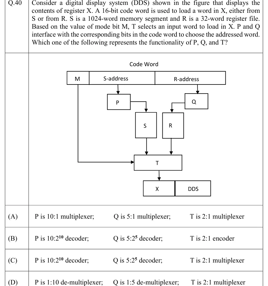
Consider a digital display system (DDS) shown in the figure that displays the contents of register X. A 16-bit code word is used to load a word in X, either from S or from R. S is a 1024-word memory segment and R is a 32-word register file. Based on the value of mode bit M, T selects an input word to load in X. P and Q interface with the corresponding bits in the code word to choose the addressed word. Which one of the following represents the functionality of P, Q, and T?
 Tap to open full size
Figure description
A box labelled 'Code Word' is split into three adjacent fields from left to right: M, S-address (wide) and R-address (wide). An arrow goes from the S-address field down into block P. An arrow goes from the R-address field down into block Q. The output of P goes (via an elbow line) down into block S (a tall box). The output of Q goes (via an elbow line) down into block R (a tall box). Block S and block R each have an arrow going down into block T (a wide box). The M field has a line running down and then right into T as a control input. The output of T goes down into register X (a box), drawn beside a box labelled DDS.
- (A)
P is 10:1 multiplexer; Q is 5:1 multiplexer; T is 2:1 multiplexer
- (B)
P is 10:2^10 decoder; Q is 5:2^5 decoder; T is 2:1 encoder
- (C)
P is 10:2^10 decoder; Q is 5:2^5 decoder; T is 2:1 multiplexer
- (D)
P is 1:10 de-multiplexer; Q is 1:5 de-multiplexer; T is 2:1 multiplexer