
IAE Academy

GATE 2025 EC Q.47: solution and answer

GATE 2025 · ECQ.47 · 2 marks · MCQ

In the circuit shown, the identical transistors Q1 and Q2 are biased in the active region with . The Zener diode is in the breakdown region with and .

If and , then the values of and (in , rounded off to one decimal place) are ______, respectively.
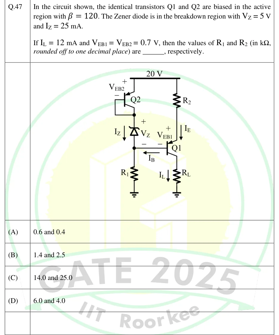
GATE 2025 EC question 47: A +20 V supply rail runs across the top.Tap to open full size
Figure from the GATE 2025 EC paper. It is part of the question.
Figure description

A +20 V supply rail runs across the top. Left branch: PNP transistor Q2 has its emitter connected to the 20 V rail; its base is shorted to its collector (diode-connected), with V_EB2 marked + at the emitter and − at the base. The Q2 collector/base node goes down to the cathode of a Zener diode (Zener drawn pointing upward, cathode at top), with V_Z marked + at the top and − at the bottom, and current I_Z shown flowing downward through it. The Zener anode (bottom node) connects down through resistor R_1 to ground, and also connects to the base of PNP transistor Q1; the base current I_B is shown flowing out of the Q1 base leftward into this node. Right branch: resistor R_2 connects from the 20 V rail down to the emitter of Q1, with current I_E flowing downward through R_2 into the emitter; V_EB1 is marked + at the Q1 emitter and − at its base. The collector of Q1 goes down through load resistor R_L to ground, with I_L flowing downward through R_L.

  1. (A)

    0.6 and 0.4

  2. (B)

    1.4 and 2.5

  3. (C)

    14.0 and 25.0

  4. (D)

    6.0 and 4.0

Answer and solution

ANSWER

and , which is option (A).

Official answer: ASource: Official answer key, GATE 2025 EC (IIT Roorkee)

  1. Assumptions, as given: both PNP transistors are in the active region with and , and the Zener is in breakdown with . Q2 has its base tied to its collector (diode-connected), and its collector/base node connects only to the Zener cathode, so Q2's whole emitter current is the Zener current . Q2 simply drops .

  2. Node voltages from the 20 V rail downward (KVL through Q2 and then the Zener): , so the Zener anode, which is also Q1's base, sits at .

  3. Emitter of Q1 (KVL across its emitter-base junction): . The voltage across is therefore .

  4. Q1's collector current flows through , so . Active-region relations: and .

  5. Ohm's law for , which carries :

  6. KCL at the node joining the Zener anode, Q1's base and the top of : the Zener current enters from above, and the PNP base current flows out of Q1's base into this node, as the figure's arrow shows. Both leave through , so .

  7. Ohm's law for (top node at , bottom at ground):

  8. So and , which is option (A).

KEY IDEA

The diode-connected Q2 and the Zener form a fixed voltage stack below the 20 V rail. That stack pins Q1's base at , and so its emitter at . then sets the emitter current across a fixed 5 V drop. carries the Zener current plus the PNP base current that flows out of Q1's base.

WATCH OUT FOR

A common slip is measuring the Zener voltage from ground and putting Q1's base at 5 V. The Zener actually sits under Q2, so what sees is . The other trap is units: volts divided by milliamps gives kilo-ohms directly, and a slip of a factor of 10 lands on option (D). The base current (0.1 mA) barely changes either value at one decimal place, but its direction matters. For a PNP it flows out of the base, so it adds to the Zener current in .

From the GATE 2025 EC paper. Every question of this paper · Download the full paper · All 13 Biasing questions, with notes

More Biasing questions