
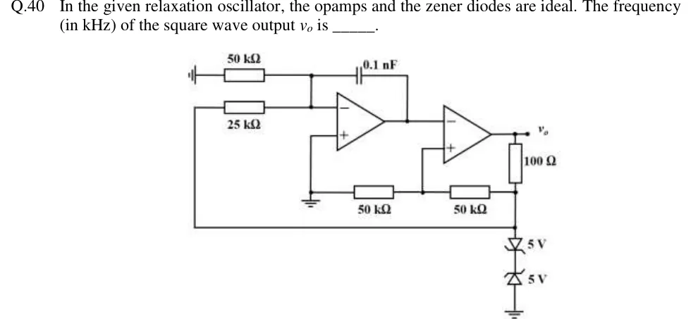
In the given relaxation oscillator, the opamps and the zener diodes are ideal. The frequency (in kHz) of the square wave output is ______.
 Tap to open full size
Figure description
Two op-amps in cascade. Op-amp 1 (integrator): its non-inverting (+) input goes straight to ground. Its inverting (−) input node connects to (i) a 50 kΩ resistor whose other end goes to a ground symbol drawn sideways at the far left, (ii) a 25 kΩ resistor whose other end is a wire that runs down the left side of the drawing and along the bottom to node A (described below), and (iii) a 0.1 nF capacitor running from the inverting input to the output of op-amp 1. Op-amp 2 (comparator): its inverting (−) input takes the output of op-amp 1. Its non-inverting (+) input goes to the junction of two 50 kΩ resistors in series along the bottom of the drawing. The left 50 kΩ goes to the ground line (the same line as op-amp 1's + input), and the right 50 kΩ goes to node A. The output of op-amp 2 is labelled v_o. From v_o, a 100 Ω resistor runs down to node A. From node A to ground there are two 5 V zener diodes back to back, joined cathode to cathode: the upper one has its anode at node A, the lower one has its anode at ground.