
IAE Academy

GATE 2026 IN Q.61: solution and answer

GATE 2026 · INQ.61 · 2 marks · NAT

In the phase-locked-loop circuit shown below, the output of the VCO is a digital square wave.

If the input is a square wave at 10 kHz, the steady state frequency of the output is ________ kHz. (rounded off to the nearest integer)
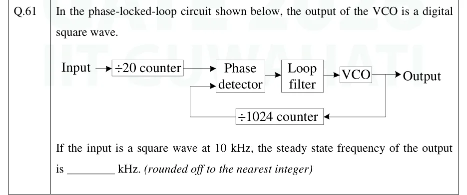
GATE 2026 IN question 61: Block diagram of a PLL, left to right: 'Input' arrow into a '÷20 counter' block;Tap to open full size
Figure from the GATE 2026 IN paper. It is part of the question.
Figure description

Block diagram of a PLL, left to right: 'Input' arrow into a '÷20 counter' block; the counter output goes to one input of a 'Phase detector' block; the phase detector output goes to a 'Loop filter' block, then to a 'VCO' block; the VCO output is labelled 'Output'. Feedback path: the VCO output is tapped and fed back (right to left) through a '÷1024 counter' block, whose output goes to the second input of the phase detector.

Answer and solution

ANSWER

The steady-state output frequency is 512 kHz. The loop locks when the output divided by 1024 equals the input divided by 20, which is 500 Hz.

Official answer: 512Source: Official answer key, GATE 2026 IN (IIT Guwahati)

  1. Reference input to the phase detector. The input first passes through the counter, so the phase detector sees

  2. Feedback input to the phase detector. The VCO output is fed back through the counter, so the phase detector's second input is at .

  3. Lock condition. Assume the loop locks, i.e. the required VCO frequency lies within its range. In steady state the two phase-detector inputs must then have the same frequency, and only a constant phase difference can remain (if the frequencies differed, the phase error would keep growing and the loop filter would keep moving the VCO). So .

  4. Solve for the output frequency:

  5. General check. A PLL frequency synthesiser with an input divider and a feedback divider gives . This is already an integer, so no rounding is needed.

KEY IDEA

When a PLL is locked, both inputs of the phase detector run at the same frequency. With a divide-by-M counter on the reference path and a divide-by-N counter in the feedback path, , so . This is how an integer-N frequency synthesiser works.

WATCH OUT FOR

Swapping the two dividers, which gives . The divider in the feedback path multiplies the output frequency and the reference divider divides it. Other slips: ignoring the counter and answering , or giving the answer in Hz (512000) when the blank asks for kHz.

From the GATE 2026 IN paper. Every question of this paper · Download the full paper · All 13 Filters & waveforms questions, with notes

More Filters & waveforms questions