
IAE Academy

GATE 2024 IN Q.52: solution and answer

GATE 2024 · INQ.52 · 2 marks · NAT

Consider the capacitive sensor circuit and its output voltage shown in the figure. The circuit is switched ON at . Assuming the opamp to be ideal, the frequency of the output voltage is ______ kHz (rounded off to two decimal places).
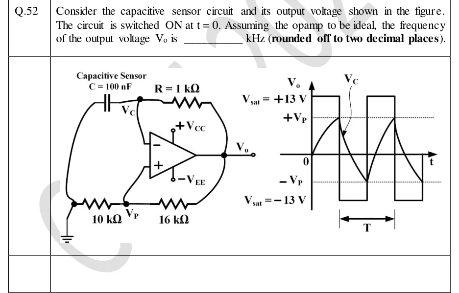
GATE 2024 IN question 52: Left: an op-amp astable (relaxation oscillator) with supplies +V_CC and -V_EE.Tap to open full size
Figure from the GATE 2024 IN paper. It is part of the question.
Figure description

Left: an op-amp astable (relaxation oscillator) with supplies +V_CC and -V_EE. A capacitive sensor C = 100 nF is connected between the inverting (−) input node, labelled V_C, and ground. A resistor R = 1 k Ω connects the V_C node to the output V_o (negative feedback path). The non-inverting (+) input node, labelled V_P, is connected to ground through a 10 k Ω resistor and to the output V_o through a 16 k Ω resistor (positive feedback). Right: waveform plot against t. V_o is a square wave switching between V_sat = +13 V and V_sat = -13 V. V_C starts at 0 at t = 0, rises exponentially to +V_P, then swings exponentially between +V_P and -V_P (dotted threshold lines), switching V_o each time it reaches a threshold. One period T is marked under the plot.

Answer and solution

ANSWER

The output frequency is ().

Official answer: 6.00 to 6.30Source: Official answer key, GATE 2024 IN (IISc Bengaluru)

  1. Identify the circuit. This is a symmetric op-amp astable (relaxation oscillator). and feed the inverting input; the / divider feeds a fraction of the output back to the non-inverting input (positive feedback). Assumption: the op-amp is ideal (no input current, instant switching) and its output sits at , as the figure shows.

  2. Feedback fraction (voltage divider). No current enters the input, so The comparator therefore switches when reaches (while ) or (while ).

  3. Start-up (first half-cycle only). At , , so and charges from 0 toward . This first interval, from 0 to , is shorter than a normal half-period (), which is why the figure marks later on. It does not set the frequency.

  4. Steady-state half-period (RC charging law). With , charges through from toward : Setting gives The discharge from toward , ending at , is the mirror image, so it takes the same time.

  5. Period. With :

  6. Frequency.

KEY IDEA

In a symmetric op-amp astable, the capacitor swings between , charging each time toward . Each half-period is , so . Here , is the resistor from the input to ground (10 kΩ) and is the one from the input to the output (16 kΩ). The value of cancels, so the ±13 V only confirms that the thresholds are ±5 V.

WATCH OUT FOR

Swapping the divider resistors. , or , gives about 3.48 kHz. Taking (the resistor ratio instead of the divider fraction) gives about 3.41 kHz. A third mistake is timing the start-up interval (0 to , which is ) as if it were a half-period; the figure marks in steady state, where swings the full to .

From the GATE 2024 IN paper. Every question of this paper · Download the full paper · All 13 Filters & waveforms questions, with notes

More Filters & waveforms questions