
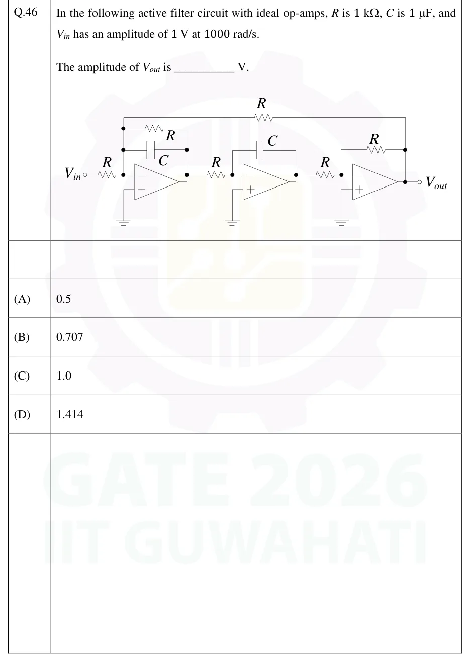
In the following active filter circuit with ideal op-amps, is , is , and has an amplitude of at .
The amplitude of is ________ V.
 Tap to open full size
Figure description
Three ideal op-amps in cascade. Every non-inverting (+) input is grounded. Op-amp 1: V_in goes through a resistor R to the inverting (−) input. Between the inverting input and the output of op-amp 1 are a resistor R and a capacitor C in parallel. A further resistor R runs along the top of the circuit from the inverting input of op-amp 1 to the final output V_out, so it is a feedback path from the end of the chain. Op-amp 2: the output of op-amp 1 goes through R to the inverting input of op-amp 2. Capacitor C is the feedback element from the output of op-amp 2 to its inverting input, which makes an inverting integrator. Op-amp 3: the output of op-amp 2 goes through R to the inverting input of op-amp 3. Resistor R is the feedback element from the output to the inverting input, which makes a unity-gain inverter. The output of op-amp 3 is V_out.
- (A)
0.5
- (B)
0.707
- (C)
1.0
- (D)
1.414