
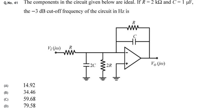
The components in the circuit given below are ideal. If and , the dB cut-off frequency of the circuit in Hz is
 Tap to open full size
Figure description
Inverting op-amp circuit. Input source V_i(j ω) connects through a series resistor R to a node X. From node X to ground there are two shunt elements in parallel: a capacitor 2C and a resistor 2R. Node X connects directly to the inverting (−) input of an ideal op-amp. The non-inverting (+) input is connected to ground. The feedback network between the output and the inverting input (node X) is a resistor R in parallel with a capacitor C. The output is taken at the op-amp output terminal as V_o(j ω) with respect to ground.