
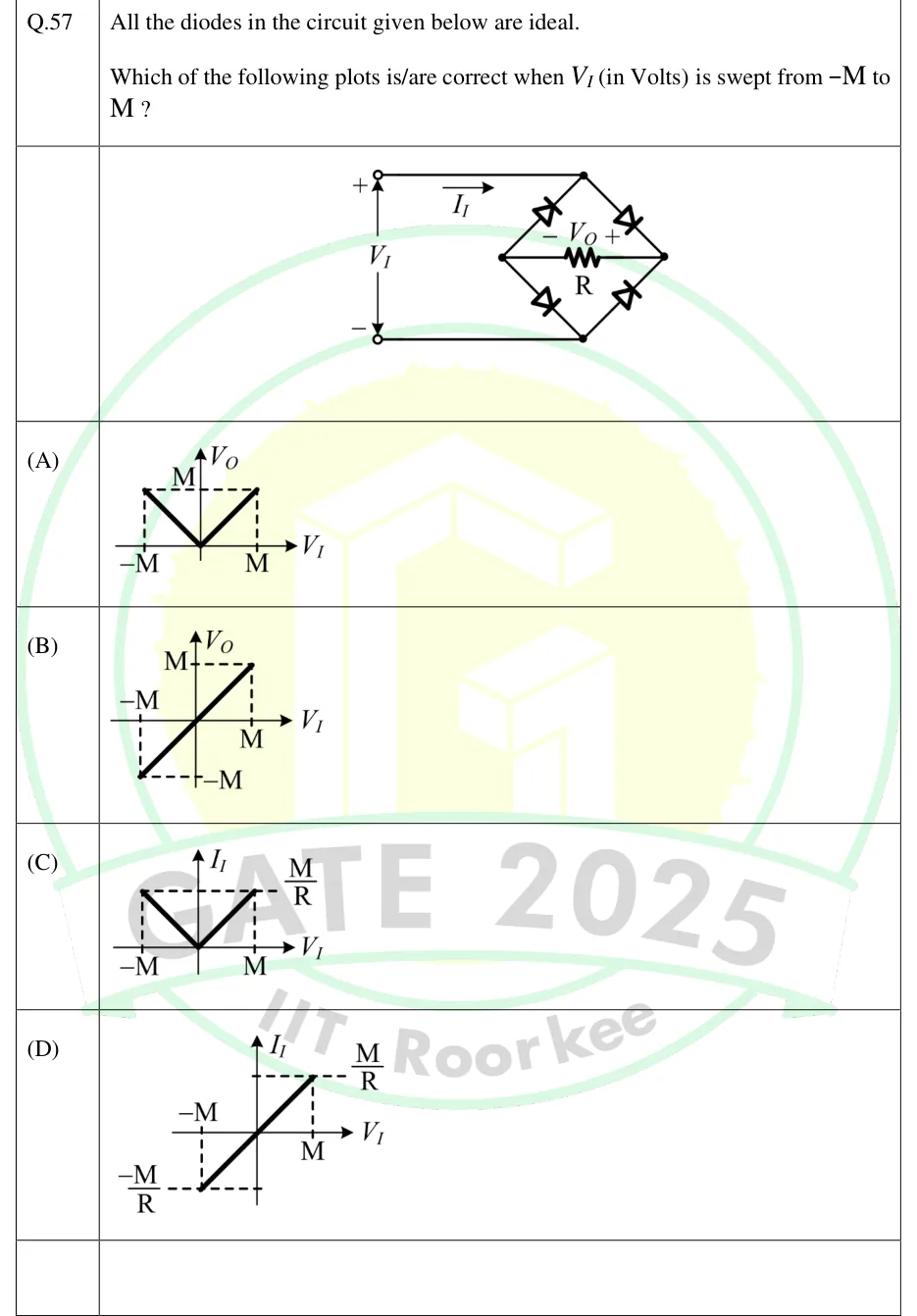
All the diodes in the circuit given below are ideal.
Which of the following plots is/are correct when (in Volts) is swept from to ?
 Tap to open full size
Figure description
A voltage source V_I with its + terminal at the top and its − terminal at the bottom. The top wire goes from the + terminal to the top node T of a diamond-shaped bridge of four diodes. A current I_I is marked on this wire with its arrow pointing right, away from the source and into the bridge. The bottom wire goes from the − terminal to the bottom node B of the diamond. A resistor R is connected between the left node P and the right node Q of the diamond, and V_O is marked across it with − at P (left) and + at Q (right). The four ideal diodes are: upper-left, anode at P and cathode at T; upper-right, anode at T and cathode at Q; lower-left, anode at P and cathode at B; lower-right, anode at B and cathode at Q. So both diodes at Q have their cathodes there, and both diodes at P have their anodes there.
- (A)
Figure — plot of (vertical axis) against (horizontal axis). It is V-shaped: at , it falls linearly to 0 at the origin, and it rises linearly back to at . Dashed lines mark the level M above .
- (B)
Figure — plot of against . It is a straight line through the origin from to . Dashed lines mark at .
- (C)
Figure — plot of against . It is V-shaped: at , it falls linearly to 0 at the origin, and it rises linearly back to at .
- (D)
Figure — plot of against . It is a straight line through the origin from to . Dashed lines mark at .