
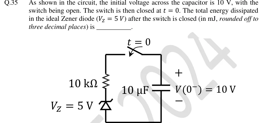
As shown in the circuit, the initial voltage across the capacitor is 10 V, with the switch being open. The switch is then closed at . The total energy dissipated in the ideal Zener diode () after the switch is closed (in mJ, rounded off to three decimal places) is ________.
 Tap to open full size
Figure description
A single series loop. Right branch: a 10 µF capacitor, top plate marked +, bottom plate marked −, labelled V(0⁻) = 10 V. Top wire: a switch that closes at t = 0, joining the capacitor's top (+) terminal to the top of the left branch. Left branch, top to bottom: a 10 kΩ resistor, then a Zener diode labelled V_Z = 5 V. The Zener's triangle points upward with its bent (Zener) bar at the top, so the cathode connects to the resistor and the anode to the bottom wire. The bottom wire joins the Zener's anode to the capacitor's bottom (−) terminal.