
IAE Academy

GATE 2023 EE Q.44: solution and answer

GATE 2023 · EEQ.44 · 2 marks · MSQ

All the elements in the circuit shown in the following figure are ideal. Which of the following statements is/are true?
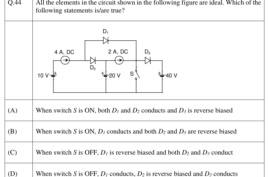
GATE 2023 EE question 44: A common bottom rail (ground) joins the negative terminals of three DC voltage sources and the lower contact of a switch.Tap to open full size
Figure from the GATE 2023 EE paper. It is part of the question.
Figure description

A common bottom rail (ground) joins the negative terminals of three DC voltage sources and the lower contact of a switch. Left branch: 10 V source, + at top; its top terminal feeds a 4 A DC current source whose arrow points right, into node P. From node P a wire rises to a top rail carrying diode D1 (anode on the left at P, cathode on the right), which comes back down at the right to node R. Also from node P, diode D2 (anode left at P, cathode right) goes along the middle rail to node Q. Node Q goes down to a 20 V source (+ at top, - to ground), and continues right through a 2 A DC current source (arrow pointing right, so current flows Q to R) to node R. At node R, the top rail from D1 comes down, switch S goes from R down to ground, and diode D3 (anode left at R, cathode right) goes right to the top of a 40 V source (+ at top, - to ground).

  1. (A)

    When switch S is ON, both D1 and D2 conducts and D3 is reverse biased

  2. (B)

    When switch S is ON, D1 conducts and both D2 and D3 are reverse biased

  3. (C)

    When switch S is OFF, D1 is reverse biased and both D2 and D3 conduct

  4. (D)

    When switch S is OFF, D1 conducts, D2 is reverse biased and D3 conducts

Answer and solution

ANSWER

(B) and (C) are true. With S ON, node R sits at 0 V, so D1 conducts and D2 and D3 are reverse biased. With S OFF, the 2 A source forces current through D3, which puts node R at 40 V. D2 then conducts, and D1 is reverse biased.

Official answer: B, CSource: Official answer key, GATE 2023 EE (IIT Kanpur)

  1. Take the bottom rail as and name the nodes. P is where the 4 A source, D1 and D2 meet. Q is the top of the 20 V source, so . R is where D1, the 2 A source, S and D3 meet. D3's cathode is held at . For an ideal diode, ON means with forward current , and OFF means with zero current. An ideal current source can sit at any voltage, so the 4 A source always pushes into P. The 10 V source is in series with it, so it does not fix .

  2. S ON: the closed switch makes . D3 then has , so D3 is reverse biased.

  3. By KCL at node P, the forced has to leave through D1 or D2. Suppose D2 conducts. Then , which would put across D1. An ideal diode cannot have a positive , so D2 cannot conduct.

  4. So D1 carries the whole , and . D2 then has , so it is reverse biased. Check at node R: flows down through S, and nothing breaks. Statement (B) is true. Statement (A) is false because D2 does not conduct.

  5. S OFF: with S open, D3 is the only way out of node R. KCL there gives . Since , . So D3 must conduct, and .

  6. Now node P. If D1 conducted, , and D2 would see . That is impossible, so D1 does not conduct. The 4 A must go somewhere, so D2 conducts: and . D1 then has , so it is reverse biased.

  7. Check: , so , which agrees with step 5. At node Q, comes in through D2 and leaves through the 2 A source, so goes into the terminal of the 20 V source. An ideal source accepts that. The ideal current sources take up whatever voltage is left: the 4 A source sits between and , and the 2 A source between and . Statement (C) is true. Statement (D) is false because D1 is reverse biased.

  8. Correct options: (B) and (C).

KEY IDEA

An ideal current source pushes its current whatever the voltage across it. So KCL at a node fed by a current source forces at least one diode leaving that node to conduct. Once you know which diode must carry the current, use the ideal-diode rule (a conducting diode has , and no diode can have ) to decide which of the rival diodes is the one.

WATCH OUT FOR

Taking the 10 V source as the voltage of node P. It is in series with the 4 A source, so it fixes neither nor the current. The second common slip is assuming D3 can be off when S is OFF. With the switch open, the 2 A source's current into node R has no other way out, so D3 must conduct and clamp R at 40 V.

From the GATE 2023 EE paper. Every question of this paper · Download the full paper · All 25 Diode circuits questions, with notes

More Diode circuits questions