
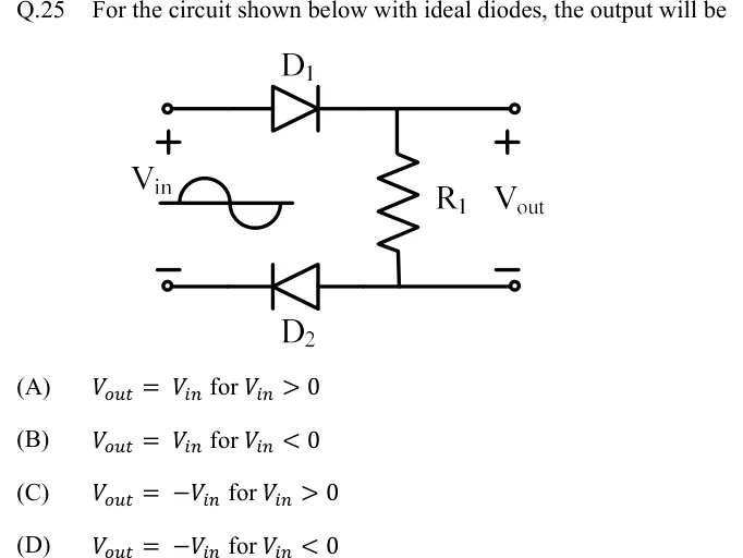
For the circuit shown below with ideal diodes, the output will be
 Tap to open full size
Figure description
A sinusoidal source V_in (drawn as a sine-wave symbol) sits between two input terminals, with + marked on the upper terminal and - on the lower one. Upper wire: from the + input terminal to the anode of diode D_1. D_1 points right, so its cathode is on the right and connects to the top output node. Lower wire: from the - input terminal to the cathode of diode D_2. D_2 points left, so its anode is on the right and connects to the bottom output node. Resistor R_1 is connected vertically between the top output node and the bottom output node. V_out is taken across R_1, with + at the top output terminal and - at the bottom output terminal.
- (A)
for
- (B)
for
- (C)
for
- (D)
for