
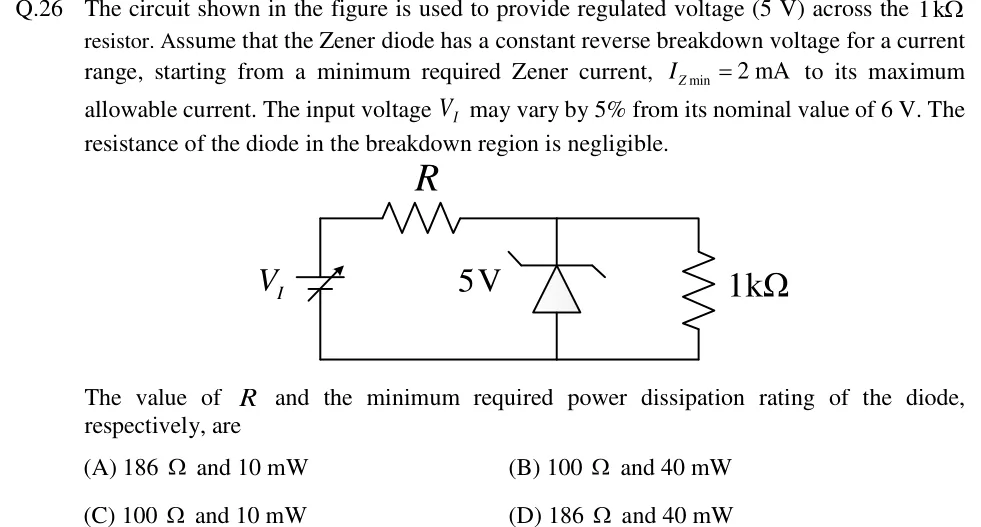
The circuit shown in the figure is used to provide regulated voltage (5 V) across the resistor. Assume that the Zener diode has a constant reverse breakdown voltage for a current range, starting from a minimum required Zener current, to its maximum allowable current. The input voltage may vary by 5% from its nominal value of 6 V. The resistance of the diode in the breakdown region is negligible.
The value of and the minimum required power dissipation rating of the diode, respectively, are
 Tap to open full size
Figure description
Zener shunt regulator. A variable DC source V_I (battery symbol with a diagonal arrow, indicating it is variable) on the left, with its positive terminal at the top. From the top of the source, a series resistor R runs horizontally to the top node. Across the top node and the bottom (ground) rail are connected in parallel: a Zener diode labelled 5 V, drawn with its cathode (bar with bent ends) at the top node and anode at the bottom rail, so it is reverse-biased; and a 1 kΩ load resistor on the far right. The bottom rail connects the negative terminal of V_I, the Zener anode and the bottom of the 1 kΩ resistor.
- (A)
186 Ω and 10 mW
- (B)
100 Ω and 40 mW
- (C)
100 Ω and 10 mW
- (D)
186 Ω and 40 mW