
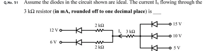
Assume the diodes in the circuit shown are ideal. The current flowing through the resistor (in mA, rounded off to one decimal place) is ____
 Tap to open full size
Figure description
A central node X (left) and a node Y (right) are joined by a 3 kΩ resistor; the current I_x is marked with an arrow pointing LEFT, i.e. from Y towards X, through the 3 kΩ resistor. Left side: two branches meet at node X. Upper branch: terminal '12 V' -> ideal diode -> 2 kΩ resistor -> node X, with the diode's cathode (bar) on the 12 V terminal side and its anode on the resistor side. Lower branch: terminal '6 V' -> ideal diode -> 2 kΩ resistor -> node X, again cathode towards the 6 V terminal and anode towards the resistor. Right side: node Y branches into three ideal diodes going to terminals '15 V' (top), '10 V' (middle) and '5 V' (bottom). Each of these diodes has its cathode (bar) on the node-Y side and its anode on the source-terminal side, so each can only pass current from its source into node Y. All terminal voltages are with respect to a common ground (not drawn).