
IAE Academy

GATE 2026 EC Q.65: solution and answer

GATE 2026 · ECQ.65 · 2 marks · NAT

Consider the ideal diodes D1 and D2 as shown in the Figure with cut-in voltage Volt and is in Volt.

The maximum voltage (Volt) of the output is ____. (rounded off to two decimal places)
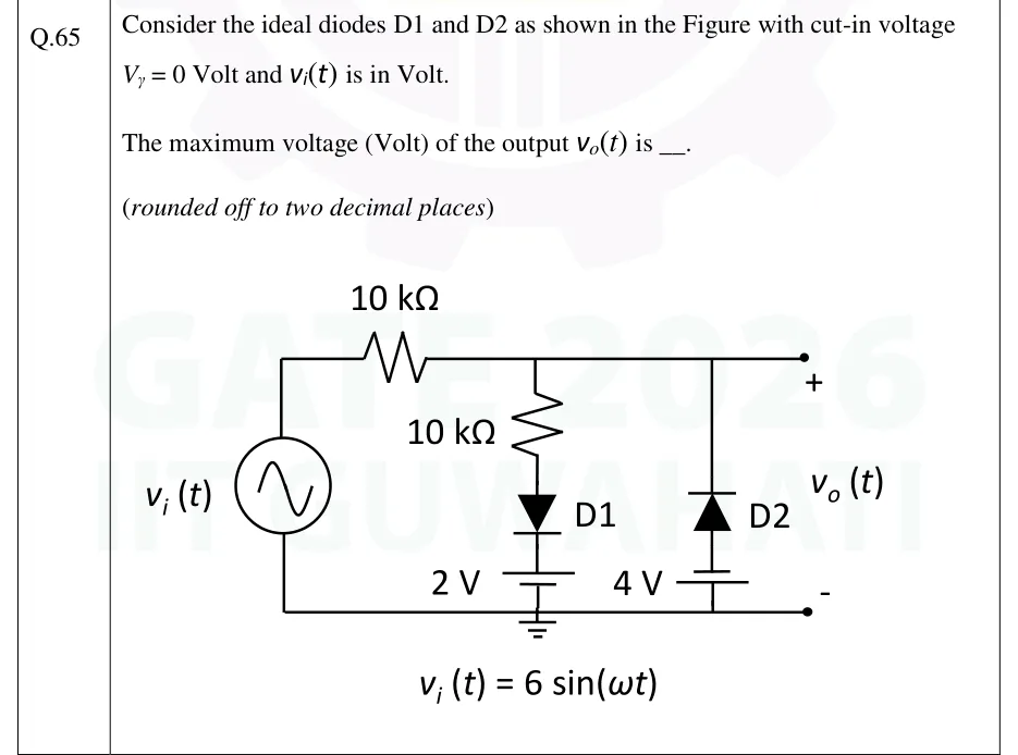
GATE 2026 EC question 65: A sinusoidal source v_i(t) = 6 sin (ω t) has its lower terminal on the bottom (ground) rail, which carries a ground symbol.Tap to open full size
Figure from the GATE 2026 EC paper. It is part of the question.
Figure description

A sinusoidal source v_i(t) = 6 sin (ω t) has its lower terminal on the bottom (ground) rail, which carries a ground symbol. Its upper terminal goes through a series 10 kΩ resistor to the top rail, and the top rail is the output node v_o(t) (+ at the top rail, − at the bottom rail). Two shunt branches run from the top rail down to the bottom rail. Branch 1: a 10 kΩ resistor, then diode D1 pointing downward (anode at the resistor, cathode below), then a 2 V battery with its long (+) plate on top, so D1's cathode sits at +2 V, and the battery's lower end on the ground rail. Branch 2, at the output: diode D2 pointing upward (cathode on the top rail, anode below), then a 4 V battery with its short (−) plate on top and its long (+) plate on the ground rail, so D2's anode sits at −4 V. Both diodes are ideal, with V_γ = 0.

Answer and solution

ANSWER

The maximum output voltage is .

Official answer: 3.70 to 4.30Source: Official answer key, GATE 2026 EC (IIT Guwahati)

  1. Read the battery polarities. The 2 V battery has its long (+) plate on top, so D1's cathode is held at . The 4 V battery has its short (−) plate on top, so D2's anode is held at .

  2. Find when each ideal diode conducts (). D1 (anode towards the output through 10 kΩ, cathode at ) can conduct only when . D2 (cathode at the output, anode at ) conducts only when . So on the positive half-cycle only D1 matters, and D2 stays reverse-biased.

  3. Region (both diodes off): neither shunt branch carries current, so no current flows in the series 10 kΩ and . (For , D2 conducts and holds at ; this affects only the minimum, not the maximum.)

  4. Region (D1 on, D2 off): one loop current flows from the source, through the series 10 kΩ and the 10 kΩ in D1's branch, into the 2 V battery. By KVL,

  5. Output voltage: Above 2 V the output therefore keeps rising, with slope . D1 does not clamp it flat, because the 10 kΩ in D1's branch sits between the output and the battery: the two 10 kΩ resistors form a divider between and .

  6. Put in the peak . Since increases with in this region, the maximum output occurs at the input peak:

  7. Check the assumed diode states at the peak: D1 current is , so D1 is on. D2 has , so D2 is off. Both assumptions hold, and .

KEY IDEA

A diode clipper with a resistor in series with the diode and its reference battery does not clip flat. Once D1 turns on, the series 10 kΩ and the branch 10 kΩ form a voltage divider between and the 2 V battery, so above 2 V the output follows and reaches 4 V at the 6 V input peak. D2, with its anode at −4 V, affects only the negative half-cycle.

WATCH OUT FOR

Treating D1 as a hard clamp and answering 2 V, which ignores the 10 kΩ resistor in D1's own branch. Another mistake is misreading the battery symbols (long plate = +). Taking D1's cathode at −2 V gives the wrong divider result, and taking D2's anode at +4 V wrongly brings D2 into the positive half-cycle.

From the GATE 2026 EC paper. Every question of this paper · Download the full paper · All 25 Diode circuits questions, with notes

More Diode circuits questions