
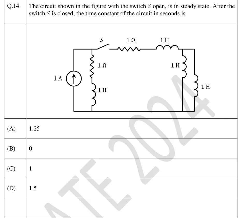
The circuit shown in the figure with the switch open, is in steady state. After the switch is closed, the time constant of the circuit in seconds is
 Tap to open full size
Figure description
Two horizontal rails: a top wire and a bottom (reference) wire. Left: an independent current source of 1 A, arrow pointing up, connected between the bottom rail and the top-left wire, so it drives 1 A up into the top-left node A. Just right of the source, a vertical branch from node A to the bottom rail made of a 1 Ω resistor in series with a 1 H inductor (resistor on top, inductor below), so this branch is in parallel with the current source. From node A the top wire runs right through switch S (drawn open; it closes at the switching instant), then a 1 Ω resistor, then a 1 H inductor, to the top-right node B. From node B two vertical 1 H inductors go down to the bottom rail, side by side, so they are in parallel with each other. No other elements. Before the switch closes, the right-hand part (1 Ω, 1 H and the two parallel 1 H inductors) is not connected to the source.
- (A)
1.25
- (B)
0
- (C)
1
- (D)
1.5