
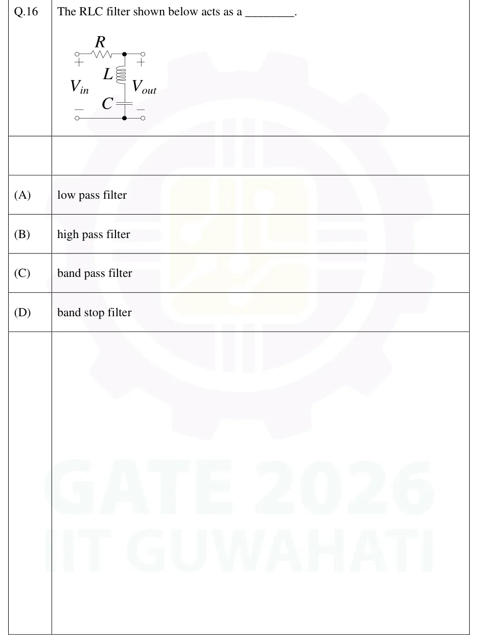
The RLC filter shown below acts as a ________.
 Tap to open full size
Figure description
Two-port RLC network. The input terminals are on the left, marked V_in (+ at top, - at bottom). A resistor R runs in series along the top rail from the V_in + terminal to a junction node (marked with a dot). From that junction the top rail continues straight to the V_out + terminal on the right. A series branch of an inductor L (upper) and a capacitor C (lower) runs from the junction node down to the bottom rail. The bottom rail is a plain wire from the V_in - terminal to the V_out - terminal and joins the lower end of the capacitor at a node (marked with a dot). V_out (+ at top, - at bottom) is therefore taken across the series L-C branch, with the output terminals open (no load).
- (A)
low pass filter
- (B)
high pass filter
- (C)
band pass filter
- (D)
band stop filter