
IAE Academy

GATE 2025 EC Q.39: solution and answer

GATE 2025 · ECQ.39 · 2 marks · MCQ

In the circuit below, is an ideal AC voltmeter and is an ideal AC ammeter. The source voltage (in Volts) is .

What should be the value of the variable capacitor such that the RMS readings on and are 25 V and 5 A, respectively?
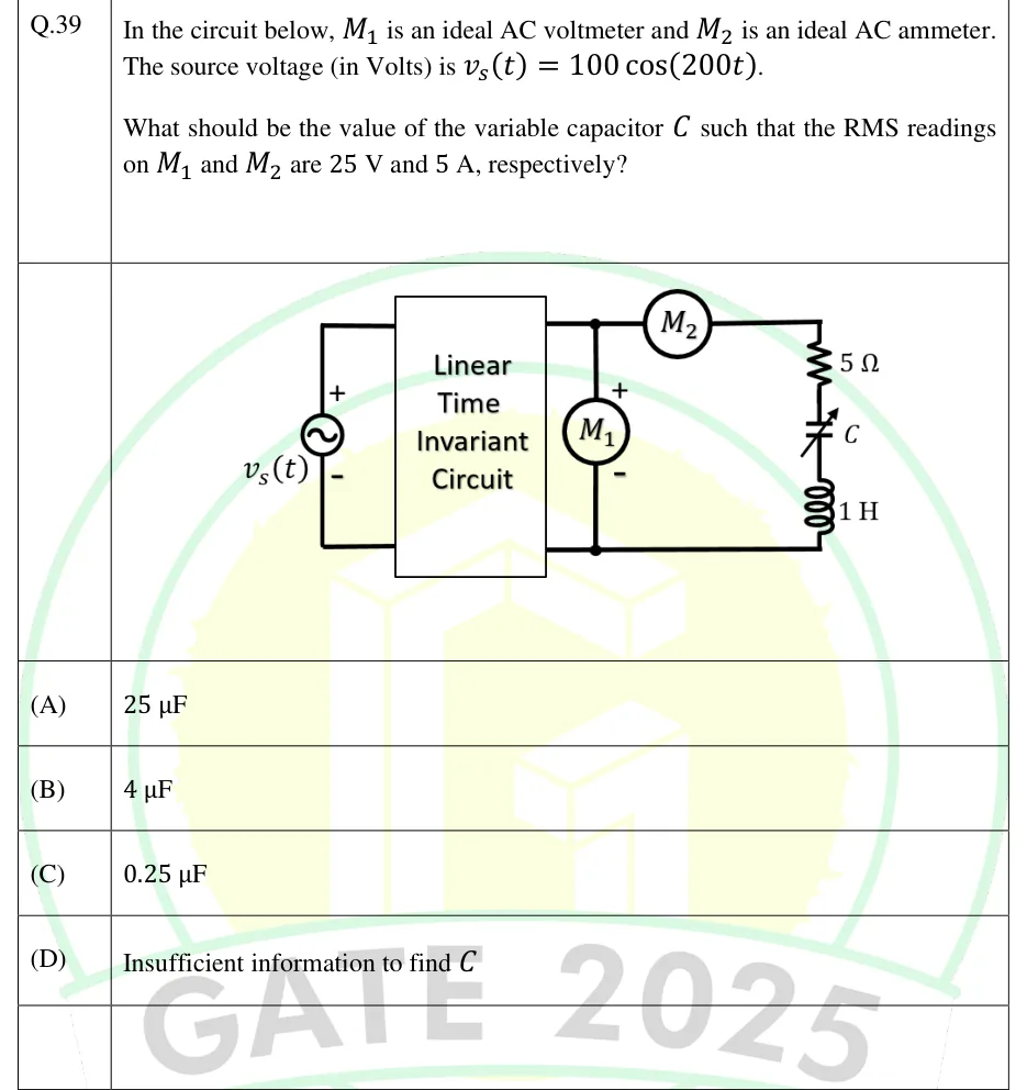
GATE 2025 EC question 39: A sinusoidal voltage source v_s(t) (+ terminal at top, - at bottom) is connected to the left-hand input terminals of a…Tap to open full size
Figure from the GATE 2025 EC paper. It is part of the question.
Figure description

A sinusoidal voltage source v_s(t) (+ terminal at top, - at bottom) is connected to the left-hand input terminals of a two-port box labelled "Linear Time Invariant Circuit". The box's right-hand output terminals form a top node and a bottom node. The ideal AC voltmeter M_1 is connected directly between these two output nodes (+ at the top node, - at the bottom node). From the top node, the ideal AC ammeter M_2 is in series along the top wire, feeding a series branch that runs down the right side: a 5 Ω resistor, then a variable capacitor C, then a 1 H inductor, returning to the bottom node. So M_1 reads the voltage across the whole series R-C-L branch and M_2 reads the current through it.

  1. (A)

    25 μF

  2. (B)

    4 μF

  3. (C)

    0.25 μF

  4. (D)

    Insufficient information to find

Answer and solution

ANSWER

(option A): the readings force , which equals , so the branch must be at resonance at , giving .

Official answer: ASource: Official answer key, GATE 2025 EC (IIT Roorkee)

  1. The box is linear and time-invariant, so in sinusoidal steady state every voltage and current at its output is at the source frequency, . We never need to know what is inside the box: the two meter readings describe the load branch completely.

  2. The ideal ammeter has zero impedance and drops no voltage, so the ideal voltmeter reads the voltage across the whole series branch of , and . reads the current through that same branch.

  3. Ohm's law in rms magnitudes: .

  4. Series branch impedance: , so with .

  5. . The branch must be at series resonance: .

  6. Check: and . They cancel, so , and matches both readings. Answer: (A).

KEY IDEA

The meters measure the load branch directly, so the unknown LTI box does not matter. The only thing the box sets is the frequency, which stays at . The readings give , which equals the branch resistance, so the net reactance must be zero (series resonance) and .

WATCH OUT FOR

Picking (D) because the contents of the box are unknown. The box only has to be LTI, which fixes the frequency at 200 rad/s, and the voltmeter and ammeter already give the branch's voltage and current. A second mistake is to use the 100 V source amplitude, or to mix peak and rms values, instead of the ratio of the two meter readings. A third is to use instead of , which gives the wrong capacitance.

From the GATE 2025 EC paper. Every question of this paper · Download the full paper · All 34 AC, power & resonance questions, with notes

More AC, power & resonance questions